tage of a CW transmitter is that it must be turned on and
off at specific intervals to produce Morse code keying
(dots and dashes). This method is very slow by modern
day standards. A better method of transmitting is AM.
AM Transmitter
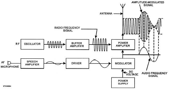
Figure 1-4, a block diagram of an AM transmitter,
shows you what a simple AM transmitter looks like.
The microphone converts the audio frequency input to
electrical energy. The driver and modulator amplify
the audio signal to the level required to modulate the
carrier fully. The signal is then applied to the power
amplifier (pa). The pa combines the rf carrier and the
modulating signal to produce the AM signal for trans-
mission.
FM Transmitter
A block diagram of an FM transmitter is shown in
figure 1-5. The transmitter oscillator is maintained at a
constant frequency by a quartz crystal. This steady sig-
nal is passed through an amplifier, which increases the
amplitude of the rf subcarrier. The audio signal is ap-
plied to this carrier phase-shift network. Here, the fre-
quency of the carrier shifts according to audio signal
variations. The FM output of the phase-shift network is
fed into a series of frequency multipliers that increase
the signal to the desired frequency. The signal is then
amplified in the power amplifier and coupled to the an-
tenna.
Two important things to remember are (1) the
amount of variation from the carrier frequency de-
pends on the magnitude of the modulating signal and
(2) the rate of variations in carrier frequency depends
on the frequency of the modulating signal.
The FM transmitter is better than an AM transmit-
ter for communications purposes because FM is less
affected by static and other types of interference. An
even better transmitter is the single-sideband transmit-
ter, or ssb. Let’s look at some of the advantages of ssb
transmitters.
SINGLE-SIDEBAND TRANSMITTER
In ssb communications, the carrier is suppressed
(eliminated) and the sideband frequencies produced by
the carrier are reduced to a minimum. This means no
carrier is present in the transmitted signal. It is re-
moved after the signal is modulated and reinserted at
the receiver during demodulation. Since there is no
carrier, all the energy is concentrated in the side-
band(s).
Figure 1-4.—AM transmitter block diagram.
1-6


