are about two pole pitches apart. Using the test
procedure described in the previous paragraph, the
maximum ammeter reading is indicated when the test
probes are connected across that portion of the winding
in which one coil shunts the remaining portion of the
winding. Hence, in all wave windings the maximum
reading will be indicated when the probes are placed on
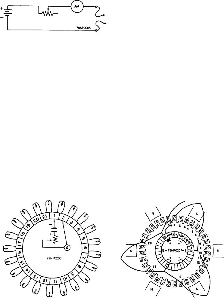
Figure 7-36.--Test circuit for messuring armature resistance.
commutator segments that are about two pole pitches
connected in series with a rheostat and a 6-volt battery
apart. The minimum ammeter reading will occur when
can be used (fig. 7-36).
the probes are placed on segments about one pole pitch
apart.
SIMPLEX LAP WINDING.-- A schematic
diagram of a simplex lap winding is illustrated in figure
With one probe stationary on segment 1 (fig. 7-38)
7-37. With the test probes placed on adjacent segments,
and the other probe moved around the commutator from
the ammeter should indicate a maximum because the
segment to segment (2, 3, 4, and so forth), the ammeter
resistance of only one coil shunts the remainder of the
readings should steadily decrease until the probes are
widing, and the resistance added to the test circuit is at
about one pole pitch apart. Then the readings should
minimum. When one test probe is moved to the next
steadily increase until the probes are about two pole
segment, the ammeter reading should decrease because
pitches apart.
the resistance between the probes has increased. With
If the probe is circled around the remainder of the
one probe stationary and the other probe contacting each
commutator, the readings should decrease and then
segment in succession around the commutator, the
increase once for each pair of poles. In the identification
ammeter indications should decrease steadily until the
of a six-pole, simplex wave winding, there should be
test probes are directly opposite each other then the
three successive decreases and increases in the meter
indications start increasing steadily as the other half of
readings. Thus, you can distinguish a simplex wave
the winding is tested. These indications are obtained
winding from a simplex lap winding by measuring the
because of the method of connecting the coils to the
resistances of the armature coils.
commutator, which is determined by the type of
winding. A simplex lap winding is the only winding that
ARMATURE TESTING AND REPAIRING.--
gives these indications.
An armature is bench tested for grounds, opens, and
SIMPLEX WAVE WINDING.-- An important
shorts at disassembly to help determine the cause of the
rule to remember for all wave windings is that the ends
dc motor or generator failure and the repairs that are
of each coil are connected to commutator segments that
required.
Figure 7-37.--Schematic of a simplex lap winding.
Figure 7-38.--Portion of a six-pole simplex wave winding.
7-28

