Home
Download PDF
Order CD-ROM
Order in Print
COMPRESSOR DISCHARGE THERMOMETER
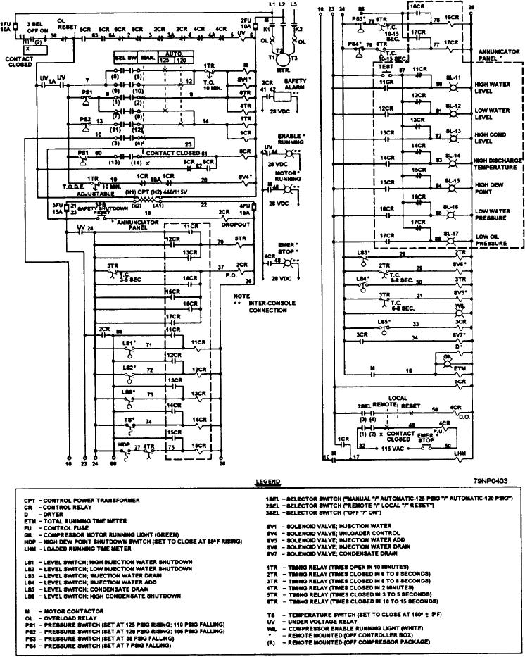
Figure 5-9.--Air compressor schematic diagram.
Electricians Mate
Page Navigation
182
183
184
185
186
187
188
189
190
191
192
Figure
5-9.--Air
compressor
schematic
diagram.
5-15