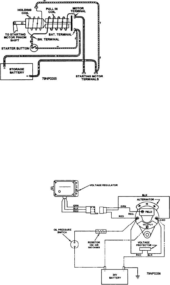
the plunger is pulled so that the pinion engages with the
flywheel ring gear. The pull-in coil draws a
comparatively heavy current necessary to complete the
plunger movement. The holding coil aids the pull-in
coil. Continuation of the plunger movement closes the
switch contacts, permitting the starter motor to crank the
engine. As soon as the solenoid switch is closed (and
the pinion shifted), the pull-in coil is shorted by the
switch contacts in the starting-motor circuit so that only
the holding coil is energized to retain the plunger in the
operated position.
When the starter switch is released, the tension of
the return spring in the drive assembly actuates the
plunger to open the circuit to the starting motor.
BATTERY CHARGING SYSTEM
For you to maintain the battery in a fully charged
Figure 5-6.--Solenoid switch diagram.
condition, the discharge current must be balanced by a
charging current supplied from an external source, such
Control Circuitry
as a battery-charging alternator. If the discharge current
The solenoid shown in figures 5-5 and 5-6 is used
exceeds the charging current for an appreciable period,
on some starting motors equipped with overrunning
the battery will gradually lose its charge. It will not be
clutch drives to close the circuit to the starting motor and
able to supply the necessary current to the electrical
also to engage the pinion with the flywheel ring gear. It
system.
is mounted on the motor frame, as shown in figure 5-5,
A belt-driven alternator is used on small boats and
and has a pull-in coil and a holding coil provided with
service crafts. The alternator has several advantages
a spring-loaded plunger. A heavy contact disk is
over the dc generator. It is smaller in size, requires less
attached to one end of the plunger, and the other end is
maintenance, and supplies charging current at idling
connected by linkage to the shift lever. Both coils are
speed.
connected in series with a starter switch located on the
instrument panel (fig. 5-6). When the starter switch is
A typical alternator electrical system wiring
operated, both coils are energized (from the battery) and
diagram is shown in figure 5-7. The three-phase ac
Figure 5-7.--A typical alternator electrical system wiring diagram.
5-11

