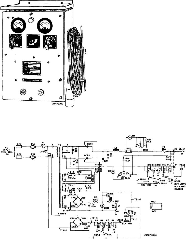
The battery charger shown in figure 5-3 has a single
unit enclosed in a dripproof enclosure. All parts are
accessible through the front hinged panel. The output
connections (jacks) for the cables to be cm.netted to the
batteries are located on the lower front of the panel. The
only moving parts of this charger are the adjustable
resistors, the rheostats, and the meters.
This type of battery charger has three selector
switches on the front panel. The output voltage is
selected by the voltage selector switch located on the
upper left side; the current selector switch is located on
the upper right side; the on/off selector switch is in the
middle between the voltage and current selector
switches.
OPERATION OF THE 24-302-BN-1
BATTERY CHARGER
The control and regulation is accomplished with
SCRs and associated circuitry. Figure 5-4 is a wiring
diagram of the battery charger. Please refer to this
diagram as you read about the operation of the battery
charger.
The first step you must take is to select the
number of cells to be charged. To do this, place the
voltage selector switch (S3) in the respective position
(3, 4, 6, 12, or 18). Then select the current rating to be
Figure 5-3.--Front view of Battery charger, model
used during charging with the current selector switch
24-302-BN-1.
Figure 5-4--Battery charger wiring diagram.
5-8

