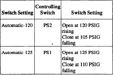
Table 5-2.--Automatic Mode Settings of a Typical LP Air
The high air temperature switch (TS) closing
The high injection water level switch (LS1)
closing
The low oil pressure switch (PS4) closing after
the timing relay (6TR) has timed closed
The low injection water pressure switch (PS3)
closing after the timing relay (6TR) has timed
closed
The low injection water level switch (LS2)
closing
The high condensate sump water level switch
(LS6) closing
Turning the selector switch (3SEL) to the ON
The high dew point temperature switch (HDP) in
position initiates the following sequence:
the dehydrator closing after the timing relay
NOTE: The following operating sequence
(4TR) has timed closed
describes control functions with the selector switch
(1SEL) in the AUTOMATIC-125 PSIG position under
The undervoltage relay (UV) contacts opening
control of the pressure switch (PS1). With the selector
The motor overload (OL) contacts opening
switch in the AUTOMATIC- 120 PSIG position, control
functions are the same but are under the control of the
A fuse (1FU, 2FU, 3FU, or 4FU) failing
pressure switch (PS2).
The operator turning the selector switch (3SEL)
1. The control relay (5CR) in the low-voltage
to the OFF position
circuit is energized. The 5CR contacts in the
The operator pressing the remote EMER STOP
high-voltage circuit close to energize the undervoltage
relay (W). The white ENABLE RUNNING light
push button, provied the selector switch (2SEL)
(WIL) is-lit on the controller door.
is in the REMOTE position
2. The UV interlocks close to provide power to
NOTE: If an automatic safety shutdown occurs, the
other parts of the control system and energize the remote
remote SAFETY ALARM will be energized by the
ENABLE RUNNING light.
control relay (2CR). If a manual shutdown occurs, the
3. The timing relay (1TR) and control relay (1CR)
remote EMER STOP lamp will be lit. If any shutdown
are energized and the following actions occur
occurs in the MANUAL operating mode, both remote
simultaneously:
and local ENABLE RUNNING and MOTOR
One set of timed-to-open (off-delay) relay 1TR
RUNNING lamps will be extinguished
contacts close to energize the motor contactor (M),
which closes the M contacts in the motor wiring leads
to start the motor. The M contacts in the low-voltage
Automatic Operation
circuit also close to energize the TOTAL RUNNING
TIME meter (ETM) and the local and remote MOTOR
Figure 5-9 is a schematic diagram of the air
RUNNING lights.
compressor control system. Please follow figure 5-9 as
A second set of 1TR contacts closes at the same
the step-by-step operation of the automatic operation is
time as the control relay (1CR). Normally closed (NC)
discussed. The controller is placed in the automatic
contacts open in the circuit to the unloader solenoid
mode of operation by the selector switch (1SEL) (table
valve (SV4) to prevent operation of the valve. Other
5-2) being placed in either the AUTOMATIC-125 PSIG
1CR normally open (NO) contacts close to energize the
LOADED RUNNING TIME meter (LHM).
or AUTOMATIC-120 PSIG position.
5-17

