
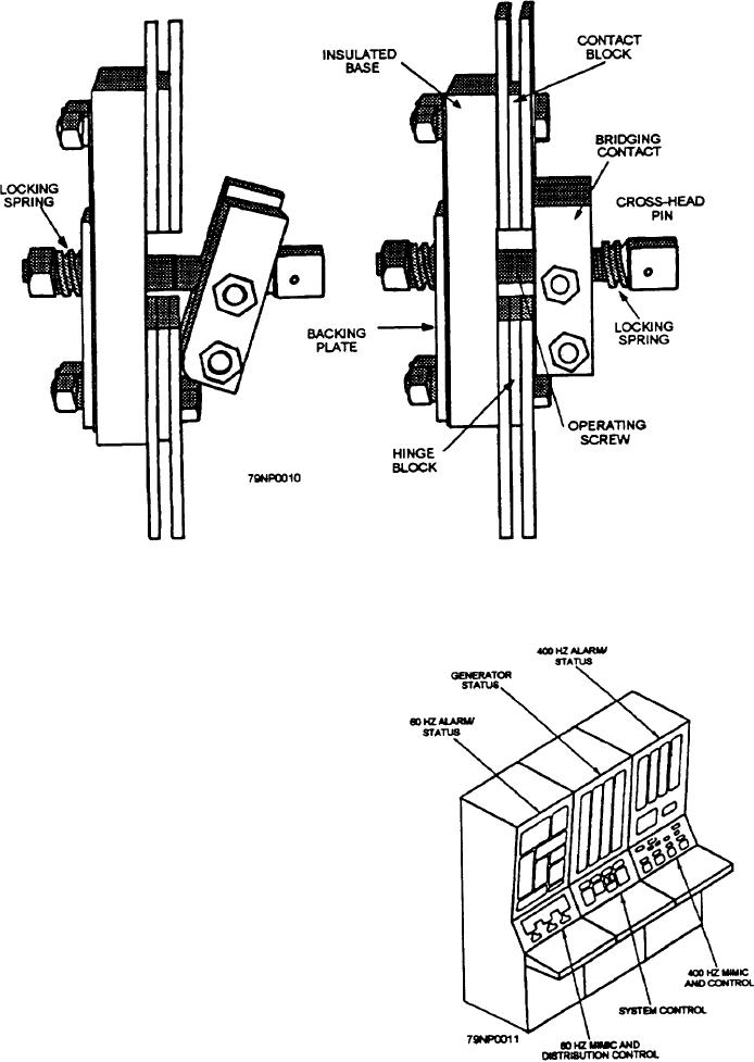
Figure 3-10.--Disconnect links.
Each of the switchboard units of a group are
connected together through disconnect links (fig. 3-10).
By removing the links between any two of the
switchboads, repairs or replacement of parts may be
accomplished without interfering with the operation of
the other units.
Control Equipment
Control of the electrical load can be accomplished
from the central control station (CCS) at the electric
plant control console (EPCC) (fig. 3-11) or by local
manual control at each GTGS and switchboard station.
The CCS and switchboard stations have the capabilities
of starting/stopping and distribution control. Only
start/stop control is available at the GTGS local control
panels.
Generator switchboards are equipped with
meters to indicate the generator voltage, current,
Figure 3-11.--Electric plant control console (EPCC).
power, frequency, and, in older ships, power factor
3-9