as required. Varying the current output reduces the
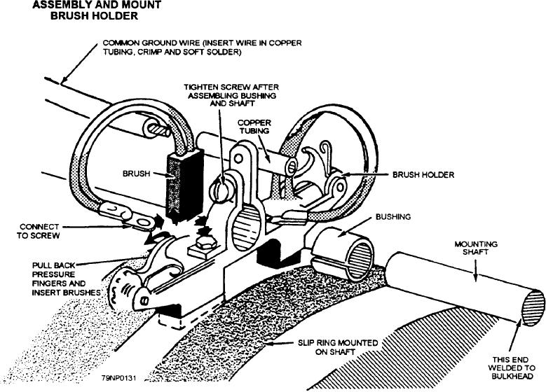
SHAFT GROUNDING ASSEMBLY.-- The shaft
grounding assembly (fig. 11-8) consists of a silver-alloy
potential difference between the hull potential and the
band, ring-fitted on the propeller shaft. The assembly
preset desired potential. Two reference electrodes are
is electrically bonded to the shaft and is usually located
installed for each controller--One is selected for the
in the shaft alley. Silver-graphite brushes ride on the
primary control, and the other serves as an auxiliary to
hard silver surface of the bands, electrically connecting
verify operation of the controlling cell and seines as a
the rotating propeller shaft to the hull. This assembly is
backup if failure of the primary cell occurs. Reference
necessary to permit the anode current that flows through
electrodes are generally located on each side of the hull,
the water to enter the propeller blades and return to the
about halfway between the anode sites. Reference
hull. A shaft grounding assembly is provided for each
electrodes are usually replaced approximate] y every 10
shaft. Ships of carrier size or larger are fitted with two
to 12 years.
brush assemblies on the silver-alloy ring.
STUFFING TUBE.-- Stufflng tubes are required
RUDDER GROUND.-- Rudders and Stabilizers
to insulate the electrical wires that pass through the hull
are grounded by brazing a braided, tinned-copper
to anodes or reference electrodes.
grounding strap at least 1 1/2 inches wide between the
Figure 11-8.--Shaft grounding assembly.
11-10

