The static timer. Provides an adjustable time
about the operation of the pump motor, the steer motor,
and the drive motor and controller.
delay between first and second speed, and one
between second and third speed, as well as a fixed
time delay between third and fourth speed.
PUMP MOTOR
The brake switch Operated by the brake pedal,
The hydraulic-lift pump motor power circuit
interrupts the drive control circuit whenever the
consists of the pump motor and contacts of the pump
brake pedal is depressed It also provides power
relay coil P. The pump motor control circuit consists of
for starting on a grade by the antirollback (ARB)
the pump relay coil P and lever valve switches that are
connection of the static timer.
actuated by a hydraulic control valve.
The static timer. Provides for controlled
To operate the lift system of the truck, you must
plugging.
close the battery switch and turn on the key switch. The
The control fuses (not shown). Protects the drive
movement of one of the lever valve switches starts the
hydraulic-lift pump motor. When the levers are
motor and the static timer against electrical
returned to neutral, the pump motor stops.
faults.
The thermal switches (not shown). Opens the
STEER MOTOR
drive and steer motor circuits in case motor frame
temperatures reach 225F.
The steer motor power circuit consists of the steer
The master accelerating switch used for controlling
motor and contacts of the steer relay coil S. The steer
truck speed is a manually operated pilot device to
motor control circuit has a relay coil S and, on the
control magnetic contractors. These magnetic
seated-type forklifts, a steer switch that is closed when
contractors control the drive motor of the vehicle. An
the operator is seated. On this type of forklift the motor
OFF position and four speeds are provided. The switch
is in continuous operation while the operator is seated.
is operated by an accelerator pedal.
This permits power steering even though the truck is not
moving.
The directional master switch determines the
direction the vehicle operates. The switch is a
DRIVE MOTOR AND CONTROLLER
three-position, manually operated, two-circuit pilot
device. It is designed for handling coil circuits of
The drive motor controller regulates the speed of the
directional magnetic contractors that must be energized
series drive motor by solid-state control circuitry
to initiate movement of the truck.
integrated with magnetically operated devices. This
The heart of a solid-state speed control system is the
SCR. Essentially, the SCR is nothing but a rectifier,
low speeds with very little battery current. This results
except that a control element (commonly referred to as
in extra hours of operation. For full-speed cruising, the
agate) has been introduced. As applied in stepless truck
solid-state system is removed from the control circuit.
control systems, the SCR is nothing but a switch.
This connects the drive motor across the battery supply.
As you read about the sequence that takes place in
The drive motor power circuit (fig. 5-38) consists
normal operation when the directional control handle is
of the drive motor with its series fields; speed-changing
moved to forward or reverse and the accelerator pedal
relay contacts 1A, 2A, 3A, and 4A; and the forward and
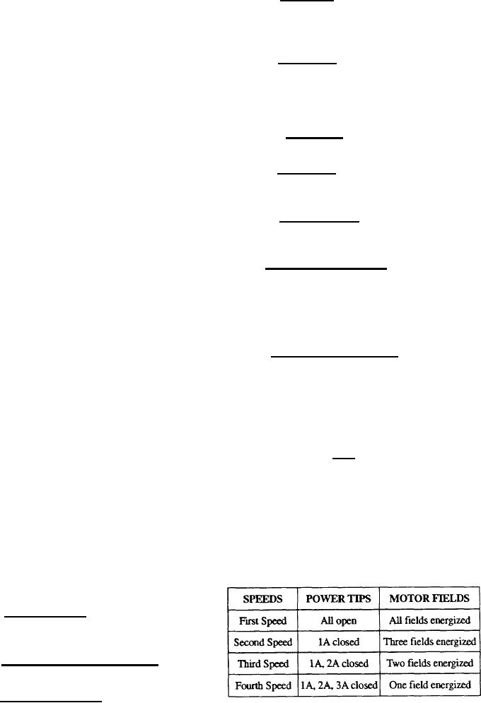
is slowly depressed, refer to figure 5-38 and table 5-4.
reversing relay contacts F and R. The functions of the
components in the drive motor control circuit are as
Table 5-4.--Drive Motor Field Connections
follows:
The accelerator pedal switches. Provides the
four accelerating speeds by controlling the series
fields of the drive motor.
The speed-changing power relay coils (1A, 2A,
3A, and 4A).
The directional relay coils (F and R).
5-57

