
operated by a separate hydraulic system that has an
Ship Control Console (SCC)
on-line power unit operating and a standby power unit
as a backup.
The SCC (fig. 5-41) operates, along with other
equipment, to control ship speed and heading and speed
A total steering gear system has two independent
lights, and it provides a display of ship performance and
sets of pump units and either set can operate the sliding
alarms status. The SCC can detect and indicate a failure
rams to cause rudder movement, while the other power
for approximately 90% of the console electronics,
unit set is offline. Each of the steering gear assemblies
indicated on the console malfunction, power supply
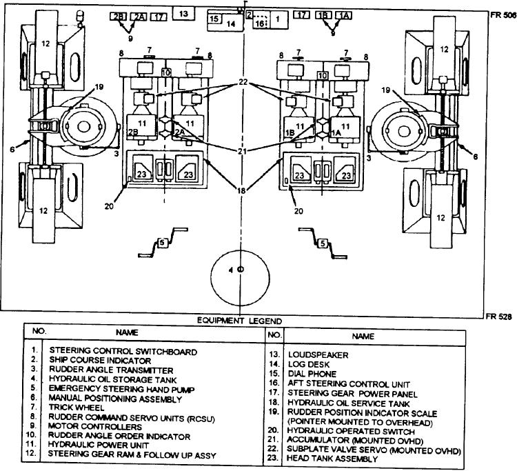
operates through the function of the following systems
malfunction, EOT/display alarm, or autopilot alarm
and components (fig. 5-40):
indicators.
Figure 5-40.--Steering gear room (plan view).
5-60