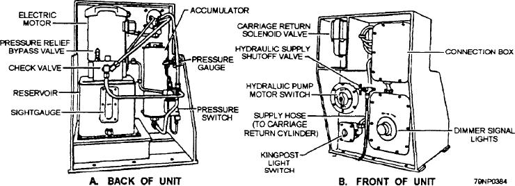
mechanically operates an electrical limit switch. This
lowering if the elevator with the arms open and unloaded
action automatically energizes the carriage return
or with the arms closed and loaded Emergency circuits
solenoid valve (fig. 5-36, view B) and allows the
bypass the normal control switches to provide a built-in
hydraulic fluid within the carriage return cylinder to
safety for emergency operation. They should never be
bleed off into the reservoir (fig. 5-36, view A). As the
used unless an emergency arises.
trolley moves all the way into the receiving head, the
ARMS ROTATION CONTROL SYSTEM.--
meeting carriage is pushed back into the INDEXED
The arms rotation control system controls the opening
position and the cylinder is collapsed. When the
and closing of the elevator arms for both normal and
meeting carriage solenoid valve is de-energized, the
emergency operations. The arms system consists of an
supply port to the cylinder is open, and hydraulic
electric motor (fig. 5-34), a speed reduction gearbox,
pressure pushes the meeting carriage into the
and a cross-shaft, worm gear mechanism. The
RECEIVED position. Upon trolley release, the
1 1/2-horsepower electric motor is bidirectional and is
jackknife and limit switch also return to their normal
watertight. It operates on 440-volt ac, three-phase,
operating positions.
60-hertz power at 1,800 rpm. The components, as a unit
An electric motor mounted vertically on top of the
and with the necessary control circuitry, function to
reservoir (fig. 5-36, view A) operates a positive
open and close the arms of the elevator.
displacement gear type of hydraulic pump located inside
MEETING
CARRIAGE
CONTROL
the reservoir, The motor is a three-phase, 440-volt ac,
SYSTEM.-- The meeting carriage (fig. 5-34) receives
60-hertz, waterproof motor with a rating of 1 1/2
and cushions the incoming missile with the trolley
horsepower at 3,600 rpm. Operation of the hydraulic
catcher and jackknife units. The meeting carriage is
pump motor is automatic and maintains the hydraulic
pushed back horizontal y about 20 inches, moving from
fluid supply pressure at about 1,000 psi. During
the fully extended RECEIVED position to the fully
operation, whenever the supply pressure within the
compressed INDEXED position. The carriage is held
accumulator is below 950 psi, the oil pressure switch
in the INDEXED position by the trolley, which is
(fig. 5-36, view A) will close electrical contacts and start
retained by the trolley latch When the trolley latch is
the pump motor operating. As the pressure inside the
released the trolley is pulled from the receiving head.
accumulator reaches 1,000 psi, the oil pressure switch
Hydraulic pressure is automatically supplied to the
electrical contacts open and stop the motor. The console
carriage return cylinder, which extends the cylinder and
operator can override the automatic controls at anytime.
moves the meeting carriage to the RECEIVED position.
TROLLEY LATCH RELEASE.-- The trolley
During operation when the trolley enters the
latch (fig. 5-34) consists primarily of a latch pin and
receiving head, the jackknife folds back and
trunnion assembly, a locking arm, a solenoid, two limit
Figure 5-36.--Carriage return hydraulic power unit: A. Back of unit: B. Front of unit.
5-54

