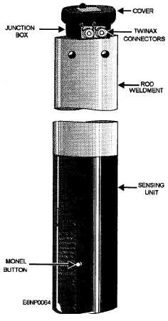
Figure 4-8.-Rodmeter.
RODMETER
The rodmeter (fig. 4-8), or sword as it is commonly
called, provides an ac signal that is proportional to
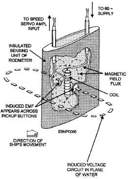
the ship’s speed. The sensing unit (fig. 4-9) of the
rodmeter is contained in a boot at its lower end. The
rodmeter operates on the principle of electromagnetic
induction, that is, when a conductor is made to move
in a magnetic field so that it cuts through the lines of
flux, an electromotive force (emf) is induced in the
conductor. In the case of the rodmeter, a 60-HZ
current is supplied to a coil in the boot of the
rodmeter. As the current flows through the coil, a
magnetic field is produced that surrounds the
rodmeter. The water, the conductor in this instance,
flows around the rodmeter and cuts through the
magnetic field. The induced voltage is felt at the
contacts, or buttons, on either side of the rodmeter.
Figure 4-9.-Rodmeter sensing unit.
The magnitude of the induced voltage is proportional
to the speed of the water flowing through the
magnetic fields. Even when the ship is stationary, a
current flowing around the rodmeter will cause a
voltage to be induced.
INDICATOR-TRANSMITTER
The indicator-transmitter displays the ship’s speed
on a dial and the distance traveled on a counter and
transmits the speed and distance information to
various equipment and remote indicators throughout
the ship.
REMOTE CONTROL
UNIT
The remote control unit, or dummy log as it is
commonly referred to, is used in place of the rodmeter
when the ship is operating in shallow water, where
lowering the rodmeter is impractical. The unit is
normally located in the main propulsion control
station. It has a spring-loaded, center-off, increase-
decrease
4-8


