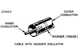
The rigid coaxial line consists of a central, insulated
wire (inner conductor) mounted inside a tubular outer
conductor. This line is shown in figure 3-13. In some
applications, the inner conductor is also tubular. The
inner conductor is insulated from the outer conductor
by insulating spacers or beads at regular intervals.
The spacers are made of Pyrex, polystyrene, or some
other material that has good insulating characteristics
and low dielectric losses at high frequencies.
Figure 3-13.—Air coaxial line.
The chief advantage of the rigid line is its ability
to minimize radiation losses. The electric and magnetic
fields in a two-wire parallel line extend into space for
relatively great distances and radiation losses occur.
However, in a coaxial line no electric or magnetic
fields extend outside of the outer conductor. The fields
are confined to the space between the two conductors,
resulting in a perfectly shielded coaxial line. Another
advantage is that interference from other lines is
reduced.
The rigid line has the following disadvantages:
(1) it is expensive to construct; (2) it must be kept
dry to prevent excessive leakage between the two
conductors; and (3) although high-frequency losses
are somewhat less than in previously mentioned lines,
they are still excessive enough to limit the practical
length of the line.
Leakage caused by the condensation of moisture
is prevented in some rigid line applications by the use
of an inert gas, such as nitrogen, helium, or argon.
It is pumped into the dielectric space of the line at
a pressure that can vary from 3 to 35 pounds per
square inch. The inert gas is used to dry the line when
it is first installed and pressure is maintained to ensure
that no moisture enters the line.
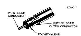
Flexible coaxial lines (fig. 3-14) are made with
an inner conductor that consists of flexible wire
insulated from the outer conductor by a solid,
continuous insulating material. The outer conductor
is made of metal braid, which gives the line flexibility.
Early attempts at gaining flexibility involved using
rubber insulators between the two conductors.
However, the rubber insulators caused excessive losses
at high frequencies.
Figure 3-14.—Flexible coaxial line.
Because of the high-frequency losses associated
with rubber insulators, polyethylene plastic was
developed to replace rubber and eliminate these losses.
Polyethylene plastic is a solid substance that remains
flexible over a wide range of temperatures. It is
unaffected by seawater, gasoline, oil, and most other
liquids that may be found aboard ship. The use of
polyethylene as an insulator results in greater
high-frequency losses than the use of air as an
insulator. However, these losses are still lower than
the losses associated with most other solid dielectric
materials.
This concludes our study of transmission lines.
The rest of this chapter will be an introduction into
the study of waveguides.
WAVEGUIDE THEORY
The two-wire transmission line used in conventional
circuits is inefficient for transferring electromagnetic
energy at microwave frequencies. At these frequencies,
energy escapes by radiation because the fields are not
confined in all directions, as illustrated in figure 3-15.
Coaxial lines are more efficient than two-wire lines
for transferring electromagnetic energy because the
fields are completely confined by the conductors, as
illustrated in figure 3-16. Waveguides are the most
3-8


