ELECTROMAGNETIC FIELDS
CHARACTERISTIC IMPEDANCE
The distributed constants of resistance, inductance,
and capacitance are basic properties common to all
transmission lines and exist whether or not any current
flow exists. As soon as current flow and voltage exist
in a transmission line, another property becomes quite
evident. This is the presence of an electromagnetic
field, or lines of force, about the wires of the
transmission line. The lines of force themselves are
not visible; however, understanding the force that an
electron experiences while in the field of these lines
is very important to your understanding of energy
transmission.
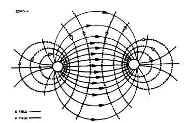
There are two kinds of fields; one is associated
with voltage and the other with current. The field
associated with voltage is called the ELECTRIC (E)
FIELD. It exerts a force on any electric charge placed
in it. The field associated with current is called a
MAGNETIC (H) FIELD, because it tends to exert
a force on any magnetic pole placed in it. Figure 3-6
illustrates the way in which the E fields and H fields
tend to orient themselves between conductors of a
typical two-wire transmission line. The illustration
shows a cross section of the transmission lines. The
E field is represented by solid lines and the H field
by dotted lines. The arrows indicate the direction of
the lines of force. Both fields normally exist together
and are spoken of collectively as the electromagnetic
field.
Figure 3-6.—Fields between conductors.
You can describe a transmission line in terms of
its impedance. The ratio of voltage to current (Ein/Iin)
at the input end is known as the INPUT IMPEDANCE
(Zin). This is the impedance presented to the transmit-
ter by the transmission line and its load, the antenna.
The ratio of voltage to current at the output (EOUT/IOUT)
end is known as the OUTPUT IMPEDANCE (ZOUT).
This is the impedance presented to the load by the
transmission line and its source. If an infinitely long
transmission line could be used, the ratio of voltage
to current at any point on that transmission line would
be some particular value of impedance. This imped-
ance is known as the CHARACTERISTIC IMPED-
ANCE.
The maximum (and most efficient) transfer of
electrical energy takes place when the source imped-
ance is matched to the load impedance. This fact is
very important in the study of transmission lines and
antennas.
If the characteristic impedance of the
transmission line and the load impedance are equal,
energy from the transmitter will travel down the
transmission line to the antenna with no power loss
caused by reflection.
LINE LOSSES
The discussion of transmission lines so far has not
directly addressed LINE LOSSES; actually some losses
occur in all lines. Line losses may be any of three
types—COPPER, DIELECTRIC, and RADIATION
or INDUCTION LOSSES.
NOTE: Transmission lines are sometimes referred
to as rf lines. In this text the terms are used inter-
changeably.
Copper Losses
One type of copper loss is I2R LOSS. In rf lines
the resistance of the conductors is never equal to zero.
Whenever current flows through one of these conduc-
tors, some energy is dissipated in the form of heat.
This heat loss is a POWER LOSS. With copper braid,
which has a resistance higher than solid tubing, this
power loss is higher.
3-3


