When the transmitting antenna is close to the
ground, it should be polarized vertically, because
vertically polarized waves produce a greater signal
strength along the earth’s surface. On the other hand,
when the transmitting antenna is high above the
ground, it should be horizontally polarized to get the
greatest signal strength possible to the earth’s surface.
RADIATION OF ELECTROMAGNETIC
ENERGY
Various factors in the antenna circuit affect the
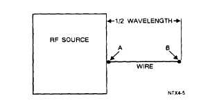
radiation of electromagnetic energy. In figure 2-3,
for example, if an alternating current is applied to the
A end of wire antenna AB, the wave will travel along
the wire until it reaches the B end. Since the B end
is free, an open circuit exists and the wave cannot
travel further. This is a point of high impedance.
The wave bounces back (reflects) from this point of
high impedance and travels toward the starting point,
where it is again reflected. Theoretically, the energy
of the wave should be gradually dissipated by the
resistance of the wire during this back-and-forth motion
(oscillation). However, each time the wave reaches
the starting point, it is reinforced by an impulse of
energy sufficient to replace the energy lost during its
travel along the wire.
This results in continuous
oscillations of energy along the wire and a high voltage
at the A end of the wire. These oscillations move
along the antenna at a rate equal to the frequency of
the rf voltage and are sustained by properly timed
impulses at point A.
Figure 2-3.—Antenna and rf source.
The rate at which the wave travels along the wire
is constant at approximately 300,000,000 meters per
second. The length of the antenna must be such that
a wave will travel from one end to the other and back
again during the period of 1 cycle of the rf voltage.
The distance the wave travels during the period of
1 cycle is known as the wavelength. It is found by
dividing the rate of travel by the frequency.
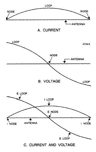
Look at the current and voltage distribution on
the antenna in figure 2-4. A maximum movement
of electrons is in the center of the antenna at all times;
therefore, the center of the antenna is at a low
impedance.
Figure 2-4.—Standing waves of current and voltage on
an antenna.
This condition is called a STANDING WAVE of
current. The points of high current and high voltage
are known as current and voltage LOOPS. The points
of minimum current and minimum voltage are known
as current and voltage NODES. View A shows a
current loop and two current nodes. View B shows
two voltage loops and a voltage node. View C shows
2-3


