COMMUNICATIONS ANTENNAS
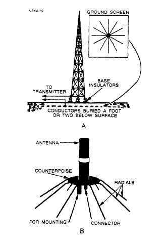
Figure 2-9.—Ground screen and
counterpoise.
The ground screen in view A is composed of a
series of conductors arranged in a radial pattern and
buried 1 or 2 feet below the surface of the earth.
These conductors, each usually 1/2 wavelength long,
reduce ground absorption losses in the vicinity of the
antenna.
A counterpoise (view B) is used when easy access
to the base of the antenna is necessary. It is also used
when the area below the antenna is not a good
conducting surface, such as solid rock or ground that
is sandy. The counterpoise serves the same purpose
as the ground screen but is usually elevated above the
earth. No specific dimensions are necessary for a
counterpoise, nor is the number of wires particularly
critical. The primary requirement is that the counter-
poise be insulated from ground and form a grid of
reflector elements for the antenna system.
Some antennas can be used in both shore-based
and ship-based applications. Others, however, are
designed to be used primarily in one application or
the other.
The following paragraphs discuss, by
frequency range, antennas used for shore-based
communications.
VERY LOW FREQUENCY (VLF)
The main difficulty in vlf and lf antenna design
is the physical disparity between the maximum
practical size of the antenna and the wavelength of
the frequency it must propagate. These antennas must
be large to compensate for wavelength and power
handling requirements (0.25 to 2 MW), Transmitting
antennas for vlf have multiple towers 600 to 1500
feet high, an extensive flat top for capacitive load-
ing, and a copper ground system for reducing ground
losses. Capacitive top-loading increases the bandwidth
characteristics, while the ground plane improves
radiation efficiency.
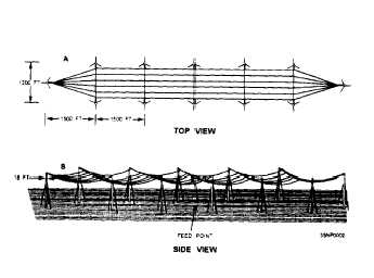
Representative antenna configurations are shown
in figures 2-10 through 2-12. Variations of these basic
antennas are used at the majority of the Navy vlf sites.
Figure 2-10.—Triatic-type antenna.
2-6


