normal. What this means for communication purposes
is that the range of frequencies on a given circuit is
smaller than normal and that communications are
possible only at lower working frequencies.
Weather
Wind, air temperature, and water content of the
atmosphere can combine either to extend radio
communications or to greatly attenuate wave propaga-
tion. making normal communications extremely
difficult. Precipitation in the atmosphere has its
greatest effect on the higher frequency ranges.
Frequencies in the hf range and below show little effect
from this condition.
RAIN.— Attenuation because of raindrops is greater
than attenuation for any other form of precipitation.
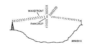
Raindrop attenuation may be caused either by
absorption, where the raindrop acts as a poor dielectric,
absorbs power from the radio wave and dissipates the
power by heat loss; or by scattering (fig. 1-13).
Raindrops cause greater attenuation by scattering than
by absorption at frequencies above 100 megahertz.
At frequencies above 6 gigahertz, attenuation by
raindrop scatter is even greater.
Figure 1-13.–Rf energy losses from
scattering.
FOG.— Since fog remains suspended in the
atmosphere, the attenuation is determined by the
quantity of water per unit volume (density of the fog)
and by the size of the droplets. Attenuation because
of fog has little effect on frequencies lower than 2
gigahertz, but can cause serious attenuation by
absorption at frequencies above 2 gigahertz.
SNOW.— Since snow has about 1/8 the density
of rain, and because of the irregular shape of the
snowflake, the scattering and absorption losses are
difficult to compute, but will be less than those caused
by raindrops.
HAIL.— Attenuation by hail is determined by the
size of the stones and their density. Attenuation of
radio waves by scattering because of hailstones is
considerably less than by rain.
TEMPERATURE INVERSION
When layers of warm air form above layers of
cold air, the condition known as temperature inversion
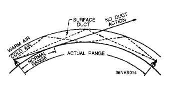
develops. This phenomenon causes ducts or channels
to be formed, by sandwiching cool air either between
the surface of the earth and a layer of warm air, or
between two layers of warm air. If a transmitting
antenna extends into such a duct, or if the radio wave
enters the duct at a very low angle of incidence, vhf
and uhf transmissions may be propagated far beyond
normal line-of-sight distances. These long distances
are possible because of the different densities and
refractive qualities of warm and cool air. The sudden
change in densities when a radio wave enters the warm
air above the duct causes the wave to be refracted back
toward earth. When the wave strikes the earth or a
warm layer below the duct, it is again reflected or
refracted upward and proceeds on through the duct
with a multiple-hop type of action. An example of
radio-wave propagation by ducting is shown in figure
1-14.
Figure 1-14.—Duct effect caused by temperature
inversion.
TRANSMISSION LOSSES
All radio waves propagated over the ionosphere
undergo energy losses before arriving at the receiving
site. As we discussed earlier, absorption and lower
1-12


