matching device and as a directional radiator. Horn
radiators may be fed by coaxial or other types of lines.
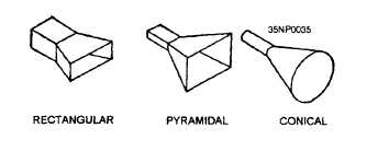
Horns are constructed in a variety of shapes as
illustrated in figure 2-43. The shape of the horn and
the dimensions of the length and mouth largely
determine the field-pattern shape. The ratio of the
horn length to mouth opening size determines the beam
angle and, thus, the directivity. In general, the larger
the opening of the horn, the more directive is the
resulting field pattern.
Figure 2-43.—Horn radiators.
FEEDHORNS
A waveguide horn, called a FEEDHORN, may
be used to feed energy into a parabolic dish. The
directivity of this feedhorn is added to that of the
parabolic dish. The resulting pattern is a very narrow
and concentrated beam. In most radars, the feedhorn
is covered with a window of polystyrene fiberglass
to prevent moisture and dirt from entering the open
end of the waveguide.
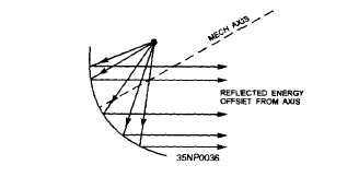
One problem associated with feedhorns is the
SHADOW introduced by the feedhorn if it is in the
path of the beam. (The shadow is a dead spot directly
in front of the feedhorn.) To solve this problem the
feedhorn can be offset from center. This location
change takes the feedhorn out of the path of the rf
beam and eliminates the shadow. An offset feedhorn
is shown in figure 2-44.
RADAR SYSTEMS
Now that you have a basic understanding of how
radar antennas operate, we will introduce you to a few
of the radar systems currently in use.
Figure 2-44.—Offset feedhorn.
AN/GPN-27(ASR-8) AIR
SURVEILLANCE RADAR
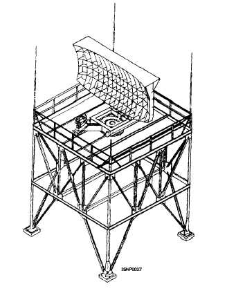
The AN/GPN-27(ASR-8) (fig. 2-45) antenna
radiates a beam 1.5 degrees in azimuth and shaped
in elevation to produce coverage of up to approxi-
mately 32 degrees above the horizon. This provides
a maplike presentation of aircraft within 55 nautical
miles of an airport terminal. The antenna azimuth
Figure 2-45.—AN/GPN-27(ASR-8) air
surveillance radar.
2-26


