The truncated paraboloid reflector may be used
in height-finding systems if the reflector is rotated
90 degrees, as shown in view C of figure 2-41. This
type of reflector produces a beam that is wide
horizontally but narrow vertically. The beam pattern
is spread like a horizontal fan. Such a fan-shaped
beam can be used to determine elevation very
accurately.
Orange-Peel Paraboloid
A section of a complete circular paraboloid, often
called an ORANGE-PEEL REFLECTOR because of
its shape, is shown in view D of figure 2-41. Since
the reflector is narrow in the horizontal plane and wide
in the vertical, it produces a beam that is wide in the
horizontal plane and narrow in the vertical. In shape,
the beam resembles a huge beaver tail. This type of
antenna system is generally used in height-finding
equipment.
Cylindrical Paraboloid
When a beam of radiated energy noticeably wider
in one cross-sectional dimension than in the other is
desired, a cylindrical paraboloid section approximating
a rectangle can be used. View E of figure 2-41
illustrates this antenna. A parabolic cross section is
in one dimension only; therefore, the reflector is
directive in one plane only. The cylindrical paraboloid
reflector is either fed by a linear array of dipoles, a
slit in the side of a waveguide, or by a thin waveguide
radiator. Rather than a single focal point, this type
of reflector has a series of focal points forming a
straight line. Placing the radiator, or radiators, along
this focal line produces a directed beam of energy.
As the width of the parabolic section is changed,
different beam shapes are produced. This type of
antenna system is used in search systems and in ground
control approach (gca) systems.
CORNER REFLECTOR
The corner-reflector antenna consists of two flat
conducting sheets that meet at an angle to form a
corner, as shown in view F of figure 2-41. This
reflector is normally driven by a half-wave radiator
located on a line that bisects the angle formed by the
sheet reflectors.
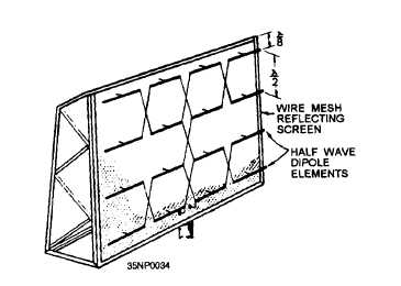
BROADSIDE ARRAY
Desired beam widths are provided for some vhf
radars by a broadside array, such as the one shown
in figure 2-42. The broadside array consists of two
or more half-wave dipole elements and a flat reflector.
The elements are placed one-half wavelength apart
and parallel to each other. Because they are excited
in phase, most of the radiation is perpendicular or
broadside to the plane of the elements. The flat
reflector is located approximately one-eighth wave-
length behind the dipole elements and makes possible
the unidirectional characteristics of the antenna system.
HORN RADIATORS
Horn radiators, like parabolic reflectors, may be
used to obtain directive radiation at microwave
frequencies. Because they do not involve resonant
elements, horns have the advantage of being usable
over a wide frequency band.
The operation of a horn as an electromagnetic
directing device is analogous to that of acoustic horns.
However, the throat of an acoustic horn usually has
dimensions much smaller than the sound wavelengths
for which it is used, while the throat of the electromag-
netic horn has dimensions that are comparable to the
wavelength being used.
Horn radiators are readily adaptable for use with
waveguides because they serve both as an impedance-
Figure 2-42.—Broadside array.
2-25


