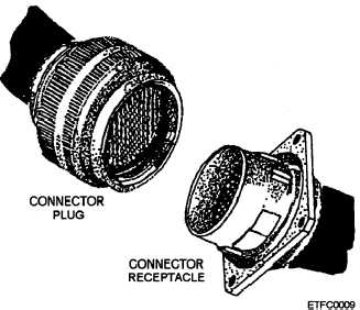
receptacle (jack) and a connector plug (fig. 2-15). The
receptacle can be located at the end of a cable or
mounted stationary. The plug can be located at the end
of pcb or cable. The actual connection (mating) of a
connector consists of pcb card-edge, electrical pins (flat
or round) and contacts, or soldered (wire to card-edge
connector). Let’s examine the types of connectors.
SINGLE-PIECE PCB OR CARD-EDGE
CONNECTORS.— Single-piece pcb or card-edge
connectors are used internally. They are the most
widely used connectors for making connections from a
pcb (plug) to a receptacle; cable, another pcb, or a larger
item such as a backplane receptacle. Figure 2-16 shows
a single-piece pcb or card-edge connector. Connection
can also be made from the pcb edge to a wire (soldered).
Terminations of conductor to receptacle include solder
and solderless (wire wrap, crimping, pin removal and
insertion,
or Mass-Termination Insulation
Displacement Connection (MTIDC) or Insulation
Displacement Connection (IDC).
TWO-PIECE PLUG AND RECEPTACLE PCB
CONNECTORS.— Two-piece plug and receptacle pcb
connectors are used internally. Two-piece pcb
connectors are basically the same as one-piece pcb
connectors except the pcb is designed with a plug (male
or female) on the card edge that plugs into a receptacle
(male or female). Pins or contacts located on either
receptacle or plug can be flat or round. See figure 2-17.
Two-piece connectors are preferred over one-piece
because they provide more resistance to shock and
vibration. Terminations of conductor to receptacle
Figure 2-15.—A connector: a plug and a receptacle.
Figure 2-16.—Single-piece pcb or card-edge connector.
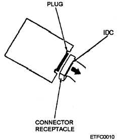
include solder (2M or basic) or solderless (wire wrap,
crimping, pin removal and insertion, or MTIDC or IDC
[fig. 2-18]).
RECTANGULAR MULTIPIN CON-
NECTORS.— Rectangular plastic- or metal-shell
receptacles and plugs can be used for internal and
external connectors. They can be flat with a single row
Figure 2-17.—Two-piece plug and receptacle pcb connector.
2-16


