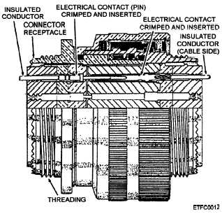
for internal and external connectors (fig. 2-21).
Circular connectors can have over 100 pins or contacts.
The contacts or pins located on either the receptacle or
plug are usually round and can be male or female.
Circular connectors can be secured to protect against
shock and vibration with either complete or partially
threaded shells (breech lock) or bayonet-style (pin and
curved slot); neither kind requires internal or external
screws for securing the mating parts.
Externally, provisions can be made for shielding
these connectors from EMI and RFI. Terminations of
conductor to receptacle include solder (2M or basic) and
solderless (wire wrap, crimping, pin removal and
insertion, MTIDC or IDC, or AMP TERMI-POINT).
Terminations of conductor to plug include solder (2M
and basic) and solderless (crimping and pin removal and
insertion). Combinations of termination are often used.
Fiber optic connectors fall into the circular
connector category.
Refer to NEETS, Module 24,
Introduction to Fiber Optics, for a discussion of the
mating of fiberoptic connectors.
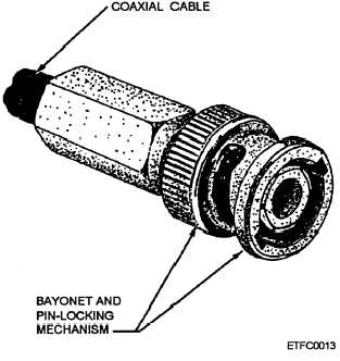
COAXIAL CONNECTORS.— Coaxial con-
nectors are designed for single, twin (twinax), and triple
(triaxial) conductors (fig. 2-22). Refer to MIL-C-17 for
connector specifications. Contacts or pins located on
either the receptacle or plug are round and can be male
or female. Coaxial connectors are secured
bayonet-style (pin and curved slot) to protect against
shock and vibration and for quick removal and
replacement.
Figure 2-21.—Circu1ar multipin connector.
Figure 2-22.—Coaxial connector.
Externally, provisions can be made for shielding
these connectors from EMI and RFI. Terminations of
conductor to receptacle include solder (2M or basic) and
solderless (wire wrap, crimping, and pin removal and
insertion). Terminations of conductor to plug include
solder (2M and basic) and solderless (crimping, and pin
removal and insertion). Combinations of termination
are often used.
COMPONENT CONNECTORS.— Although we
may not think of it as a connector, a wire attached to a
component’s lead also forms a connection. The most
commonly used methods of securing a wire to a
component’s lead are soldering and wire wrapping. For
example, pushbutton indicators use wire wrap
connections to secure a conductor(s) to its pin(s). Wire
wrapping is often preferred because it is quick to
remove and install, and it is strong. Also, you do not
have to apply heat to the conductor. This prevents
damage to the conductor’s insulation that can be caused
by using a soldering iron.
Internal Connectors
Rather than have wires running everywhere inside
the computer frame or cabinet and between the units,
various methods are used to connect the conductors
from point to point and to organize the conductors.
Connectors are used inside the computer to
interconnect the major individual units of the computer.
Individual conductors are used to route each signal
between the connectors of the major units and to
2-18


