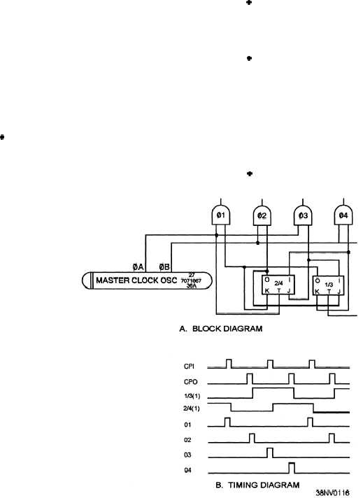
frequency stability. Figure 4-41 is an example of a
timing circuit (block and timing diagram) using an
oscillator and flip-flop combination. Notice how with
the use of a ring counter (flip-flops), we can generate
additional phases that can be used for more complex
functions involving multiple operations.
CAUTION
REMEMBER, COMPUTER CIR-
CUITS CONTAIN ESDS DEVICES. ONLY
PERSONNEL WITH ESDS TRAINING
SHOULD HANDLE ESDS DEVICES!
TOPIC 7—COMPUTER DATA TYPES
AND FORMATS
Different types or kinds of data can be processed by
a computer. The types are as follows:
l Bit —The smallest data element or operand is the
bit. Individual bits are used primarily in status
indicating and flag registers. The two possible states (0
or 1) indicate either ON/OFF, TRUE/FALSE, or other
two-state conditions.
Depending on the type of computer, single bits in a
memory word can be addressable by a single
instruction. Larger computers and some of the newer
microcomputers have this capability. Most mainframe
computers and some newer microprocessors have
machine instructions that allow for single-bit operations
(set, clear, or test). If a processor cannot address a single
bit, there are software algorithms (small programs) that
can combine a number of microinstruction to perform
single bit operations.
. Nibble —The next larger data element or
operand is the nibble. A nibble is a 4-bit grouping or
half-byte of data. Nibbles are used to store a single
binary coded decimal (BCD) digit.
. Byte —Probably the most commonly accessed
data element is the 8-bit byte. Microcomputer
memories can use a single byte, two bytes, or more.
Bytes form the basis for operand operations. In
addition, each 8-bit byte can store a single alphanumeric
character in American National Standard Code for
Information Interchange (ASCII) format or another
coding system.
It can also hold a binary number
equivalent to 25510.
l Word —For computers with 16-bit or larger
computer words, there are two more data elements. The
Figure 4-41.—Example of an oscillator and flip-flop combination: A. Block diagram; B. Timing diagram.
4-24


