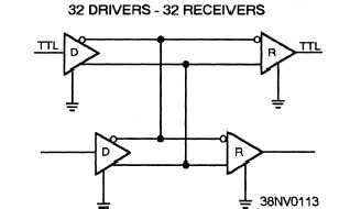
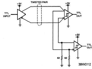
Figure 4-37.—Example of differential point-to-point line
drivers and receivers connected in parallel.
* Differential drivers and receivers —Differential
drivers and receivers are used over long distances for
high-speed communications. They are usually twisted
pairs of wires or coaxial cables. Differential types can
be point-to-point (fig. 4-37) or multiple source and
destination (fig. 4-38).
Single-ended and differential line drivers and
receivers are commonly used by some of the following
interfaces:
l NTDS Input/Output (MIL-STD 1397)
l RS-232 (EIA RS-232)
l RS-422 (EIA RS-422)
l RS-449 (EIA RS-449)
Line drivers drive digital information over both
long and short distances to other equipments in a
computer system. Line drivers do this by generating
large voltage or current output digital signals from small
voltage and current TTL or MOS digital signals to travel
over transmission lines.
Figure 4-38.—Example of differential multiple source and
destination line drivers and receivers.
Line receivers receive digital information from
both long and short distances from other equipments in
a computer system. By the time the data reaches the
line receiver from a line driver, the voltages are very
low. The receiver operates with a very low threshold to
detect these signals. Line receivers are usually used for
long distances for parallel transmission.
TOPIC 6—TIMING CIRCUITS
Control and timing circuits comprise a very
important area of a computer. A computer’s operations
rely on commands/instructions being controlled
(enabled and disabled) at specific times. Timing
circuits are used to ensure the proper timing of enables
and disables throughout the computer. Timing pulses
are used to enable and disable specific circuits. This
permits specific operations to begin and others to be
ended. The return of these pulses a short time later
could cause an enabled circuit to be disabled and
another circuit to be enabled. In this way, operations
previously begun are ended and anew set of operations
is started.
When a program is installed and operating, circuits
are enabled and disabled through a sequential process
that continues until one of the following events occurs:
The program is completed
A programmed stop is reached
A fault condition occurs
A pulse generator of a type determined by computer
design provides the main timing signals for any given
type of computer.
These pulse generators are
commonly termed master clocks or reference
generators.
They usually operate at a frequency or
pulse repetition rate determined by the maximum rate
at which the computer handles data. The master clock
is the key to the timing circuits in the computer. It will
set in motion the computer’s main timing circuits.
From the main timing circuits, other timing circuits for
the various other areas (arithmetic, memory, and I/O)
can be enabled or disabled. The clock will produce
electrical pulses with extreme regularity. The speed of
the computer’s clock is determined by an oscillator.
TIMING CIRCUIT COMPONENTS
Timing circuit components consist of wave
generators and wave shapers. In computers, waveforms
must be turned on and off for specific lengths of time.
The time intervals vary from tenths of microseconds to
several thousand microseconds. Square and
4-22


