ROM Chips
l
l
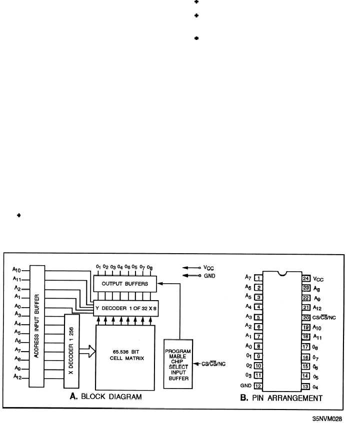
A ROM chip is one or more chips on a pcb located
in a rack or backplane/motherboard. Figure 6-35 is an
example of a 64K ROM block diagram and IC with pin
l
connections. Notice the items used to obtain the ROM
Magnetic (fig. 6-36)
Transistors-Bipolar or MOS (fig. 6-37; MOS
ROM)
Fusible links
Regardless of the type of material used for ROM,
address. The heart of the chip is the 65,536-bit memory
the cell array is masked to a particular 0/1 arrangement
array. This array is masked with a ROM data pattern.
The desired word in the array is selected by the X and
to form the permanent data needed for ROM operations.
Y decoders. The 13 address lines are the inputs to these
two decoders. As the address is decoded, the output
word is presented to the output buffers. The chip select
line is used to enable or disable the tristate mode of the
output buffers. The eight output lines come from the
output buffers. Pure ROM chips are manufactured with
the desired software instructions or data installed.
READ-ONLY MEMORY (ROM)
MATERIALS
The types of materials that make up a ROM also
vary. ROMs can consist of the following types of
materials:
READ-ONLY MEMORY (ROM)
OPERATIONS
As stated, ROM operations are characteristic of
main memory operations except you cannot write to
ROM. This means ROM operations use no write
pulses or equivalent and no data input buffers are
needed. The basic operation of ROM, like a main
memory address, is to use the permanent data stored in
the ROM address. Since we are studying the computer
and its internal operations, the operation in this case is
the execution of an instruction contained at a ROM
address. But you can see where if you needed to use the
same data at a particular location repeatedly (for
l Hardwired (fig. 6-36)
example, a look-up table), this concept could be used.
Figure 6-35.—ROM chip: A. Block diagram; B. Pin arrangement.
6-28


