a static RAM cell and its associated circuitry in block
form. Each memory cell can latch, or store, data in a
stable state. Information is written into and readout of
the cell through the column lines. The characteristics
of flip-flops keep the flip-flop in its present state and
allow you to read the data out of the cell without
changing its state when the row-line is activated.
Similarly data is written through the column line only
when the row-line is activated, so only one cell in each
column is selected. A read/write control signal controls
reading and writing operations. The zero or one state
in the cells can be held indefinitely as long as proper
power supply levels are maintained.
D-type and R-S type flip-flops are commonly used
for SRAMs. The flip-flops can be made of either
bipolar or MOS transistors. MOS yields a higher
density but lower access speed. Bipolar RAMs have a
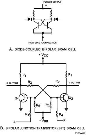
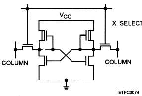
higher access speed but take up more space. Figure
6-28, frames A and B, and figure 6-29 illustrate
schematic diagrams of individual bipolar and MOS
RAM cells. Figure 6-28, frame A, is a diode-coupled
Figure 6-28.—Examples of SRAMs: A. Diode-coupled bipolar
SRAM cell; B. Bipolar junction transistor (BJT) SRAM
cell.
Figure 6-29.—SRAM MOS cell.
bipolar static RAM cell; figure 6-28, frame B, is bipolar
junction transistor (BJT) static RAM cell; and figure
6-29 is a static RAM MOS cell. As stated, the RAM
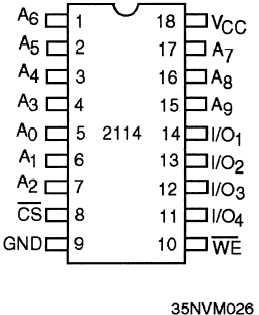
chip is mounted in a logic array on a pcb. Figure 6-30
is an illustration of an IC chip, with pin connections
used in a static bipolar or MOS RAM.
RAM chips come in various configurations and
sizes. The number of IC RAM chips needed for a
computer’s RAM memory is determined by the
requirements and memory size of the computer. Let’s
use an example IC to discuss the operation of a RAM
chip, which includes the architecture, address selection,
and read/write cycles.
Static RAM Organization and Operation
Our example RAM uses a 1 K by 4 configuration,
1024 words that are 4 bits in length. Many groups of
lK by 4 RAM chips can be grouped together with
simple support logic to form larger memory systems. A
Figure 6-30.—SRAM IC chip with connections.
6-23


