chapters and topics.
They include the number
systems, data routing circuits (adders/subtractors),
timing, instructions, and operand/registers.
In this topic, we discuss the instructions, timing,
and operand/registers and how they apply to the ALU
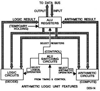
and the ALU operations. Figure 5-14 shows a
representative block diagram of an ALU of a
microcomputer. Chapter 4 of this volume and NEETS
Module 13, Introduction to Number Systems and Logic
Circuits, provide a review of number systems,
adder/subtractor circuits, timing, instructions, and
operands/registers. Also refer to NEETS 13 for detailed
information of the types of number systems and
information basic to all number systems; their
identification, operations (addition and subtraction
including radix-minus-1
complement and
radix-minus-2 complement computations), and
conversion. They are discussed in more detail, and it
would benefit you to review them to gain a better
understanding of how they apply in the ALU
operations.
INSTRUCTIONS
The instructions tell the CPU which type of
mathematical or logical calculation the ALU will
perform. They will also tell the CPU the location of the
data on which the ALU will perform the calculations
and where to store the results. Results can be used
immediately or stored for use later. Special codes
within the instructions can also affect arithmetic or
logical operations. They can be used for branching or
setting flag registers.
Figure 5-14.—Representative block diagram of an ALU.
TIMING
Timing in the ALU is provided by the CPU’s timing
circuits. Larger computers have their own arithmetic
timing circuits independent of the CPU’s timing
circuits. In this case, arithmetic timing is initiated by a
command from the CPU’s main timing chain and the
length of the arithmetic timing chain is dependent upon
the specific instruction.
OPERANDS/REGISTERS
The registers and operands provide the computer
the sources of the data needed to perform the
calculations. They also provide the destination for
results. Computers can be designed to include the use
of whole-word, half-word, and quarter-word
operands and the use of single-length a n d
double-length word/operands to carry out the
arithmetic operations. Double-length memory words
or operands will be used for mathematical operations in
which the size of the result would be greater than the
length of either of the two registers used to provide
inputs to the ALU or the operands being input to the
ALU are larger than a single word. The sign bit in
double-length memory words or operands is the most
significant bit (msb). Flag registers of one to three bits
may be used by the ALU to indicate the status of the last
arithmetic or logical operation. The last arithmetic or
logical calculation used to set a flag register is often
followed by a branching operation. Some of the items
indicated by flag registers include the following:
l Equal to zero (= 0)
l Greater than (>)
l Less than (<)
. Positive sign (+)
l Negative sign (–)
l Carry or borrow
Q Overflow
Other items used in the ALU include selectors and
counters. The selectors are used to transfer the data
between the various registers (accumulators) used in the
ALU. Counters are used to keep track of shifts used in
the various arithmetic and logical calculations.
5-19


