to an AN/SRA-33 or OA-9123 antenna coupler. The
coupler output is then fed to an antenna.
Uhf Receive
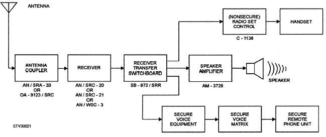
A basic block diagram of a uhf receive system is
shown in figure 2-9. Most of the components are the
same as those used in the transmit function. We will,
therefore, identify by specific designator only the
components that are unique to the receive function.
The receive signal is picked up by the antenna and fed
to the receive side of the transceiver through the
antenna coupler. The receiver output is connected
to an SB-973/SRR receiver transfer switchboard. It is
then connected to either the nonsecure or secure voice
system, depending upon the received transmission
mode.
When a nonsecure signal is received, the output of
the receive transfer switchboard is fed to either the
radio set control or to the AM-3729 speaker amplifier,
or both, depending on user preference.
If a secure voice transmission is received, the
output of the switchboard is connected to the secure
voice equipment and decrypted. This output is fed to
the secure voice matrix. The secure voice matrix
output is fed to the RPU, where the signal is converted
back to its original form.
SUPERHIGH-FREQUENCY
COMMUNICATIONS
As we discussed in the previous chapter, two
primary uses of the superhigh-frequency (shf) band are
microwave and satellite communications. The
AN/FSC-79 SHF terminal and satellite com-
munications will be covered in the next chapter. In the
following paragraphs, we will discuss line-of-sight
and tropospheric scatter microwave communications.
MICROWAVE COMMUNICATION
SYSTEMS
Microwave systems, such as the AN/FRC-84 and
AN/FRC-170(V), are used to relay multiplex signals
from point to point. A simplex relay system pro-
vides one-way communications and consists of a
transmitting terminal, a certain number of repeaters,
Figure 2-9.—Uhf receive.
2-9


