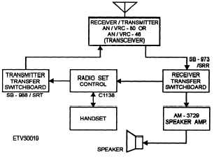
Figure 2-6.—Shipboard hf receive system.
set control. The output of the radio set control is then
fed to the switchboard.
The transmitter transfer switchboard allows
operators to select the proper transmitter for the
selected frequency. The AN/URT-23 transmitter
receives its input from the switchboard and changes
the signal to a modulated rf signal that is fed to the
AN/SRA-34, 56, 57, 58, or AN/URA-38 antenna
coupler. The antenna coupler matches the output
impedance of the transmitter to the input impedance of
the antenna. Antenna couplers also allow more than
one transmitter to be connected to the same antenna as
long as certain conditions are met. When the signal
reaches the antenna, it is radiated into the atmosphere.
Shipboard Hf Receive
A typical shipboard hf receive system is shown in
figure 2-6. A transmitted signal similar to the one
previously discussed is received by the antenna and
converted from electromagnetic energy to electrical
energy. The signal is fed to an antenna patch panel
where it can be distributed to any number of receivers.
In figure 2-6, a receiver (R-1051/URR, R-2368/
URR, or R-1903/URR) converts the rf signal into
either a teletype signal (fsk) or voice. The receiver
output is then fed to the SB-973/SRR receiver transfer
switchboard. The teletype signal from the switchboard
follows the same path used by the low-frequency
signal we discussed earlier. Identical pieces of
equipment are used. The voice signal from the receiver
switchboard is sent to the C-1138 radio set control and
Figure 2-7.—Vhf transmit and receive system.
fed to a handset. The voice signal also can be sent from
the switchboard to an AM-3729 remote speaker
amplifier and then to a speaker. This allows the user to
listen to the signal without having to hold the handset.
VERY-HIGH-FREQUENCY
COMMUNICATIONS
The Navy uses the very-high-frequency (vhf) band
for mobile communications such as bridge-to-bridge,
among boat crews, and for amphibious operations and
landing parties.
Vhf Transmit
A typical vhf transmit and receive system is shown
in figure 2-7. On the transmit side, the operator, at a
remote location, talks into the handset. The handset is
2-7


