
The air brake can be set or released.
Function Control
The air clutch can be engaged or disengaged
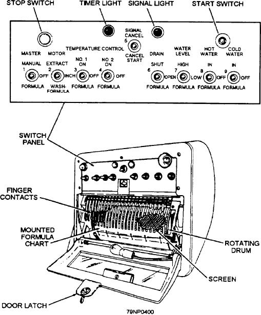
The automatic control timer (fig. 5-52) is the
The proper drive motor can be energized or
function control system for the washer-extractor.
Command and control signals are routed by finger
de-energized
contacts and/or switches in the control timer to sequence
The chart motor can advance the formula chart
functions and cycles within an operation during formula
(formula mode).
or manual mode.
The washer balance system can operate.
FORMULA MODE.-- A programmed formula
The washer door can be opened.
chart (fig. 5-53) is mounted on the rotating drum/copper
screen inside the control timer. During the formula
COMMAND CIRCUITRY.-- The 24-volt ac
mode, the drum rotates and finger contacts press against
command circuit generates command signals through
the chart. As a finger contact passes over a slot in the
the action of finger contacts and/or toggle switches. The
chart, it touches the copper screen. This completes an
command signals are routed throughout the washer to
electrical circuit and generates a command signal. Each
finger contact controls a different command signal. The
and solenoid valves sequence and control the duration
chart can control the wash operation by programming
of functions and/or cycles during a wash operation.
the time and duration of finger contact on the screen.
Figure 5-52.--A typical automatic control timer.
5-70