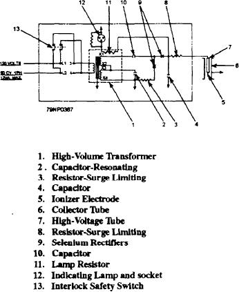
When the operating voltage drops below its minimum
to convert the electrical power to high voltage 10,000
requirement the lamp will go out.
volts dc. As you read this section refer to figure 5-19.
The access cover safety switch (13) is an interlock.
The power pack and circuitry are shown in figure
With the cover removes the contacts are open and
5-19. The circuit is a half-wave voltage doubler,
de-energize the primary of the power supply.
consisting of a high-voltage transformer (1), two
selenium rectifiers (9), and two capacitors (4 and 10).
The components of the precipitator are the ionizer
The power supply assembly is the self-regulating type
electrode (5) and the electrode chuck and high-voltage
commonly known as a constant-voltage transformer.
tube (7). The assembly is held inside the collector tube
The resonating winding (X3-X4) connected to the
(6) by an insulator. The insulator also serves to
resonatiing capacitor (2) serves to hold the power supply
electrically insulate the high-voltage assembly.
voltage at a constant level when the primary input
voltage varies. The resonating circuit is designed to
SUMMARY
help limit the output power.
The high voltage from the power supply is
The vent fog precipitator is a simple, rugged,
connected to a surge limiting resistor (8), which limits
essential piece of equipment. By following posted
the current of an arc that might occur and provides
maintenance procedures, it will remain a reliable,
protection for the capacitors.
operational piece of equipment.
The negative output of the power supply is
connected to ground through a surge limiting resistor
PROPULSION SHAFT
(3). This resistor limits the feedback current due to an
TORSIONOMETER
arc. It provides additional protection to the capacitors
through the ground terminal of the precipitator. The
The propulsion shaft torsionometer is a device used
proper operation is indicated by a lamp (12) that is
to measure the torque and (optionally) the rpm of a
connected to a resistor (11). A portion of the supply
ship's rotating propulsion shaft accurately. Of the types
output voltage is used for the neon indicating lamp.
available in the fleet, the basic principles are the same.
By accurately measuring the torsional twisting of a
ship's propulsion shaft, you can calculate the load
(torque) on the ship's main engine. Using this figure,
the load on the shaft can be calculated into shaft
DESCRIPTION
Through the use of various sensors and components,
the shaft torsionometer detects the slight twisting and
(optionally) the rpm of the ship's propulsion shaft. Then
the torsionometer produces a proportional signal and
uses the signal to drive appropriate indicators located
near the ship's engineering console or on the bridge.
Shaft horsepower readings may also be displayed at
various remote locations, such as the pilothouse or the
chief engineer's office, using repeaters or remote
displays.
The optional rpm system uses an rpm probe to
receive signals from a shaft mounted assembly. The
signals are then processed by the rpm conditioner and
sent through shipboard cables to the appropriate
Figure 5-19.--Vent fog precipitator wiring diagram.
indicators.
5-32

