In view 1 of figure 3-63, view B, the signal is fed
into arm b and in-phase outputs are obtained from
the a and c arms. In view 2, in-phase signals are fed
into arms a and c and the output signal is obtained
from the b arm because the fields add at the junction
and
induce
E
lines
into
the
b
arm.
If
180-degree-out-of-phase signals are fed into arms a
and c, as shown in view 3, no output is obtained from
the b arm because the opposing fields cancel at the
junction. If a signal is fed into the a arm, as shown
in view 4 , outputs will be obtained from the b and
c arms. The reverse is also true. If a signal is fed
into the c arm, outputs will be obtained from the a
and b arms.
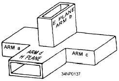
MAGIC-T HYBRID JUNCTION.— A simpli-
fied version of the magic-T hybrid junction is shown
in figure 3-64. The magic-T is a combination of the
H-type and E-type T junctions. The most common
application of this type of junction is as the mixer
section for microwave radar receivers.
Figure 3-64.—Magic-T hybrid junction.
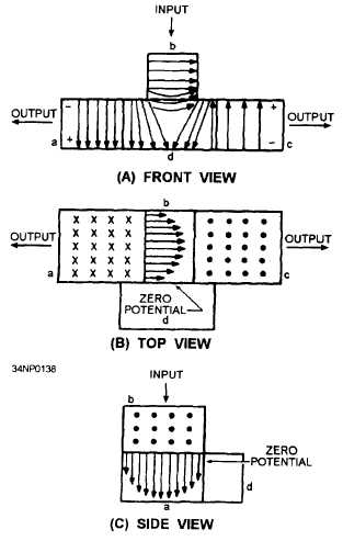
If a signal is fed into the b arm of the magic-T,
it will divide into two out-of-phase components. As
shown in figure 3-65, view A, these two components
will move into the a and c arms. The signal entering
the b arm will not enter the d arm because of the zero
potential existing at the entrance of the d arm. The
potential must be zero at this point to satisfy the
boundary conditions of the b arm. This absence of
potential is illustrated in views B and C where the
magnitude of the E field in the b arm is indicated by
the length of the arrows. Since the E lines are at
maximum in the center of the b arm and minimum
at the edge where the d arm entrance is located, no
potential difference exists across the mouth of the d
arm.
Figure 3-65.—Magic-T with input to arm b.
In summary, when an input is applied to arm b
of the magic-T hybrid junction, the output signals from
arms a and c are 180 degrees out of phase with each
other, and no output occurs at the d arm.
The action that occurs when a signal is fed into
the d arm of the magic-T is illustrated in figure 3-66.
As with the H-type T junction, the signal entering the
d arm divides and moves down the a and c arms as
outputs that are in phase with each other and with the
input. The shape of the E fields in motion is shown
by the numbered curved slices. As the E field moves
down the d arm, points 2 and 3 are at an equal
potential. The energy divides equally into arms a and
c, and the E fields in both arms become identical in
shape. Since the potentials on both sides of the b arm
are equal, no potential difference exists at the entrance
to the b arm, resulting in no output.
3-30


