Disk Formatting Operations
Disk memory sets can format disks in a variety of
modes to match the host computer’s operating system.
The formatting of a disk pack is very similar to that of
a floppy disk in that the tracks and sectors are written
on each data surface. The locations of the tracks are
controlled by the servo tracks that are prerecorded on
disk surface. The number of sectors per track is
selectable by either the SECTOR SELECT switch or a
set sector size command from the computer. In the file
management mode, the disk will have nine sectors per
track, with 512 32-bit words per sector.
Formatting a disk can be done offline using the
status/maintenance panel entries or online using the
format disk command. A disk pack can be partitioned
so that part of the disk pack is formatted in one mode
and another part of the disk pack is formatted in a
different mode.
If a disk pack is partitioned, the
operating system must be able to operate with the two
modes.
Write Operation
A write operation is initiated by the computer via
an external function. This external function defines
how many words are to be written and where on the disk
they will be written. The disk memory set then receives
the data and stores it in buffer memory.
Once the proper cylinder and track have been
reached, the first word is transferred from buffer
memory to the write data holding register. The write
data holding register transfers the data to a shift register
that converts it to a nonretum to zero (NRZ) serial pulse
train. This serial data is then sent to the disk drive’s
NRZ-to-MFM converter via the B cable read/write data
line.
The NRZ-to-MFM converter converts the pulse
train into MFM data and sends it to the write drivers.
The write drivers develop the proper write current for
the heads to record data on the disk. When the entire
word is written, a signal is sent to the controller,
indicating that the disk is ready to write the next word
and the cycle is repeated.
Read Operation
A read operation is also initiated by an external
function defining cylinder, track, head, and number of
words to be read from the disk. The heads are
positioned to the right cylinder address, and the data is
read from the disk. The serial MFM data is converted
to a digital NRZ pulse train and sent to the controller’s
shift register.
The shift register gates in each bit and transfers the
data to the read data holding register. The read data
holding register transfers the word to the buffer memory
where it is stored until it is transferred to the computer.
MAGNETIC DISK PACK CARE AND
HANDLING
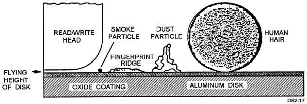
Because of the rotation speed of the disk pack in a
disk memory set, the heads are designed to float or fly
on a cushion of air. The distance the heads fly above
the disk is called the flying height of the heads. As
densities of disks have increased, the flying height of
the heads has decreased to a point where any
contaminant is larger than the flying height of the head.
Figure 10-17 shows an example of the flying height of
the head compared with common contaminants such as
smoke, dust, fingerprints, and hair.
WARNING
Never attempt to remove a disk pack from
a drive until all rotation of the disk pack has
stopped.
Figure 10-17.—The flying height of a disk read/write head compared to common contaminants.
10-22