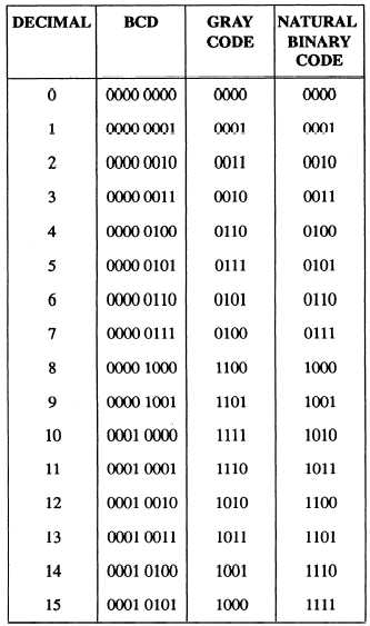
Table 13-1.—Comparison of Binary-Coded Decimal (BCD),
Gray Code, and Natural Binary Code
Synchro Systems
The term synchro is an abbreviation of the word
synchronous. It is the name given to a variety of rotary,
electromechanical, position sensing devices. Synchro
signals are used to transmit the angular position (0 to
360 degrees) of a rotor shaft in a synchro transmitter.
When the signals are applied to one or more synchro
receivers, the rotor shaft-in each receiver is positioned
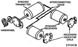
to match the transmitter’s shaft position (figure 13-4).
In this example, the receiver shaft in turn drives an
indicator dial to display the transmitted information.
The combination of synchro transmitter and
receivers is called a synchro system. There are two
major classifications of synchro systems: torque
systems and control systems.
Figure 13-4.—Torque synchro system transmitter and
receivers.
Torque systems provide torque or turning force to
drive light loads such as indicator dials, pointers, or
other mechanical outputs.
Control synchro systems provide an electrical
output used to control the power that performs
mechanical work. The control synchro normally feeds
a control transformer, not a control receiver. The
control transformer output is fed to devices such as a
servo system to control larger systems and devices.
The synchro signals converted by CDS equipment
may be either control synchro signals or torque synchro
signals; however, control synchro signals are preferred
because they are generally more accurate than torque
synchro signals.
OPERATING VOLTAGES AND FRE-
QUENCIES.— Most shipboard synchro systems
operate on a supply voltage of 115 volts ac at a
frequency of 60 or 400 Hz. Synchros operating at 115
volts 400 Hz are generally more accurate than the 60-Hz
synchros. Most newer weapon systems use 400-Hz
synchros exclusively.
SINGLE-SPEED, MULTISPEED, AND
DUAL-SPEED SYNCHRO SYSTEMS.— The
accuracy of the data to be transmitted is a factor in any
synchro system.
If the data covers a wide range of
values, then the basic synchro system is unable to detect
small changes in the data. When this happens, the
accuracy of the system decreases. Multispeed synchro
systems were developed to correct this deficiency.
Multispeed synchro systems use more than one
speed of data transmission. The speed of data
transmission is the number of times the synchro
transmitter rotor must turn 360 degrees to transmit a full
range of values. In a 1-speed system, one rotation of
the transmitter rotor covers the full range of values. The
13-5


