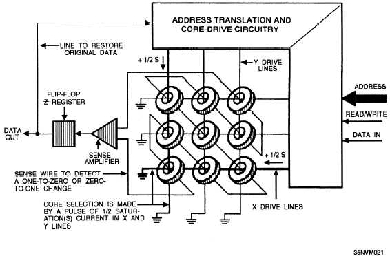
lines. Figure 6-13 is an illustration of a portion of a core
memory plane in a stack. Each stack contains a
temperature sensor to detect temperatures in the stack.
The memory capacity of a core storage device is
determined by the number of memory planes in the
memory stack. By varying the number of X and Y drive
lines in each array (64 by 64, 128 by 128, and so on)
and the number of memory planes in a memory stack,
great flexibility can be achieved in the design of a core
storage device’s memory word length and number of
addressable memory words. Stacks are usually divided
into an upper and lower configuration for address
selection and bit storage.
Three-wire magnetic core matrices allow for greater
numbers of cores because less wiring is required. A
single three-wire memory plane can provide 9 bits of
storage over 32K addresses. Three-wire memory planes
(core modules) are known as large plane memory.
Core Address Selection
The address selection process in core memory requires
some unique circuitry. Because of the complex design
of core memory, the address register and the translator
use selectors and drivers to select the correct memory
address. The address register bits are used to translate the
bits to make the following address word bit selections:
. X and Y secondary selection
. X and Y primary selection
l X and Y diode selection
l Stack selection
. Inhibit half stack upper and lower
The circuitry associated with the address word bit
selection includes the following:
X and Y secondary selectors—provide enables
for the secondary X and Y drive circuitry
X and Y primary selectors—provide enables for
the primary X and Y drive circuitry
X and Y read/write diode selectors—enable the
X and Y read drive line or the X and Y write drive
line for one of four quadrants in all four of the
memory stacks
Inhibit selectors—activated only when writing
zeros
Core Storage Read/Write Cycle
A cycle of events takes place whenever data is
stored in or retrieved from core. Let’s take a look at
how data is read from core memory and then written or
restored back into core memory.
READ CYCLE.— To determine the state of a core,
read current is applied to both drive lines (X and Y or
digit and word) passing through the core or cores
addressed. Read current is designed to change the state
Figure 6-13.—Portion of a core memory plane in a stack.
6-12


