Controls and Indicators (KCMX)
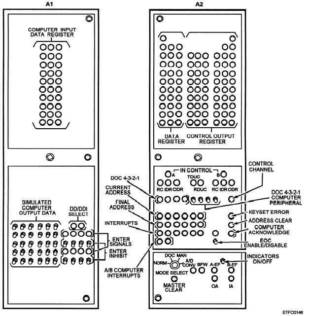
The front panels of the KCMX (figs. 13-12 and
13-13) contain all the controls and indicators used by
operating personnel.
The chassis behind the front
panels (A1, A2, A3, and A4) and the power supply
chassis in the bottom unit (PS1) can be unlatched and
run out like drawers for access to the logic board racks
inside. Signals can be observed at the appropriate test
points, which are given in the equipment prints. Power
supply fuses appear on panel AS (power control
assembly); test points for the power supply can be found
by extending chassis PS1 outward.
Power Control Assembly (A5)
The power control assembly at the top of the unit
(figure 13-10) contains the BLOWER ON/OFF switch
and indicator, main POWER ON/OFF switch and
indicator, running time meter, 3-phase BLOWER
POWER fuses, and a 1-amp fuse for the -26.5 vdc power
supply. An amber TEST MODE indicator will light
whenever the MODE SELECTOR switch (panel A2) is
in any position except NORM.
The A5 assembly also contains over-temperature
warning indicators and bypass circuitry. The red
Figure 13-12.—KCMX front panels (A1/A2).
13-20


