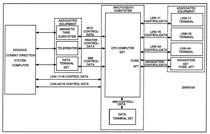
Figure 7-10.—The C2P system block diagram for ACDS Block 0 platforms.
on an ACDS Block 0 platform is very similar to the
system that is installed on an AEGIS Model 4
platform. Figure 7-10 illustrates the system block
diagram of the C2P for ACDS Block 0 platforms.
Link messages generated in the ACDS computer
are sent to the C2P computer where they are formatted
for transmission on the proper link (Link-4A, Link-11,
or Link-16). Depending on the mode of operation and
operator entered parameters, some messages may be
sent over two or more data links. For example, it is
not uncommon for Link-11 messages to be
transmitted over Link-11 and Link-16. The C2P
computer stores the data in a central database, called
the normalized data base, and then formats the data in
the proper message format for the link system(s) being
used.
Messages received by the various data links are
processed for errors by the C2P computer and sent to
the proper destination. Received messages can also
be reformatted for retransmission on a different link.
A Link-11 or Link-4A message received by a C2P
platform can be reformatted into a Link-16 message
and retransmitted on Link-16.
SYSTEM CONFIGURATION
The hardware block diagram of the equipment
used in the C2P system is shown in figure 7-11. The
AN/UYK-43(V) is a general-purpose, large scale,
tactical computer used to store and execute the C2P
software. The C2P configuration of the AN/UYK-43
consists of the following major modules:
Two central processor units
Two input/output controllers and adapters
Six expanded time volatile memory units
One embedded memory subsystem (EMS)
with two embedded mass memory storage
devices (EMMSD)
A major change in the configuration of the
AN/UYK-43A(V) is the EMS and its associated
EMMSDs. The EMS consists of two 383 megabyte
7-12


