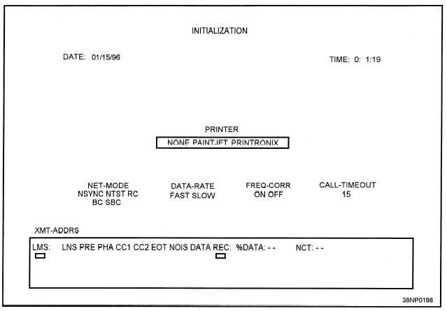
Figure 5-5.—The LMS-11 Initialization display screen.
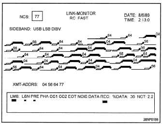
The top lines of the link monitor display screen
report ends with the interrogation of the next PU in
contain the header information. The LMS-11 mode is
in the top center. The link mode is centered just under
the LMS-11 mode. In figure 5-6, this is RC FAST.
This means the link is in Roll Call mode, fast data
rate. The right side of the header displays the date and
time. The left side of the header information allows
the operator to enter the NCS address and the
sideband to monitor. The LMS-11 uses the address
77 as a default for NCS. However, recall from
chapter 2, that 77 is an illegal address and would not
be used in an active link. Since NCS never sends an
interrogation to itself, the LMS-11 uses this address to
designate NCS.
The display sweeps from left to right and from top
to bottom. The display is color-coded and uses a
stair-step pattern that is easy to understand. The
display of a single NCS report and the meaning of the
colors and levels is shown in figure 5-7. Figure 5-8
shows how the different messages appear on the
LMS-11 link monitor screen. Note that the NCS
the polling sequence.
Figure 5-6.—The link monitor display screen.
5-10


