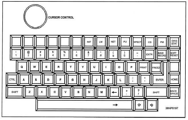
Figure 5-4.—The LMS-11 keyboard.
The analog-to-digital converter converts the
Link-11 audio signal into a digital signal for use by
the LMS-11. This digital signal is then transferred to
the computer where the FFT converts it to a frequency
domain. The Fast Fourier Transform consists of a
complex mathematical formula used to determine the
phase shift of a signal.
AUDIO INTERFACE UNIT. —The audio
interface unit connects the upper sideband (USB) and
lower sideband (LSB) audio signals from an HF radio
or the USB from a UHF radio to the LMS-11. The
audio signals are input to the analog-to-digital
converter of the control processing unit. The audio
interface unit does not add a load to the audio signal.
DUAL 3.5-INCH FLOPPY DISK DRIVE
UNIT. —The dual 3.5-inch floppy drive unit is used
to load the LMS-11 programs and to record Link-11
data. The disk drives use 788 Kbyte, double-sided,
double-density disks.
POWER CONTROL UNIT. —The power
control unit provides the control, distribution, and
conditioning of the 115 VAC input power.
Control/Display Group (CDG)
The CDG consists of a color graphics monitor and
a keyboard. The monitor displays operator-entered
data and system operation. The keyboard provides the
operator interface with the LMS-11.
COLOR DISPLAY MONITOR. —The color
display monitor is capable of displaying both
composite and RGB video. The computer generates
composite video during the start-up and testing of the
LMS-11. The RGB input with an external sync is
used for displaying graphics during normal LMS-11
operations. The monitor is also equipped with a
speaker and audio input to provide the operator with
the capability of monitoring the Link-11 audio signal.
KEYBOARD. —The keyboard is mounted on a
tray under the monitor. Under the tray, there is a
5-8


