from poor connections or reduced copper in the circuit.
Inspect cable ends at the point of connection for heavy
strain or overheating.
Shore-power cables are rated at 400 amperes,
Check switchboard meters to ensure that the total load
on shore-power cables does not exceed the combined
rating of shore-power cables. Total shore-power load in
amperes should be no more than 400 times the number
of shore-power, three-phase cables connected per phase.
PHASE-SEQUENCE INDICATOR
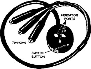
A phase-sequence indicator is used when you are
connecting shore-power to your ship to ensure proper
Figure 3-46.--Phase-sequence indicator.
phase relationship between ship power and shore power.
following safety procedures. Determine that the
An approved type of phase-sequence indicator (fig.
shore-power busing and cables are de-energized by
3-46.) has a miniature, three-phase induction motor and
using a voltage tester that has just been checked with a
three leads with insulated clips attached to the ends.
known energized power source.
Each lead is labeled A, B, and C. The miniature motor
can be started by a momentary contact switch. This
NOTE: Moving energized shore-power cables is
switch is mounted in the insulated case with a switch
prohibited.
button protruding out the front of the case to close the
switch. When the motor starts turning, you can tell its
SUMMARY
direction of rotation through the three ports in the front
of the case. Clockwise rotation would indicate correct
In this chapter, the major components of an ac
phase sequence. You can stop the motor by releasing
distribution system were covered. You must remember
the momentary contact switch button.
that there are many different types of systems and
components other than the ones described in this
UNRIGGING SHORE POWER
chapter. Also, you must remember that no work on
electrical equipment should be done without using the
When you disconnect shore power, observe the
proper technical manual.
same safety precautions outlined in the connecting
sequence except for those regarding meggering cables
For additional information about ac distribution
and checking phase orientation and phase rotation.
systems,. refer to Naval Ship's Technical Manual,
Again, tag shore-power breakers and disconnect
chapters 300, 310, 320, and 491.
3-40

