
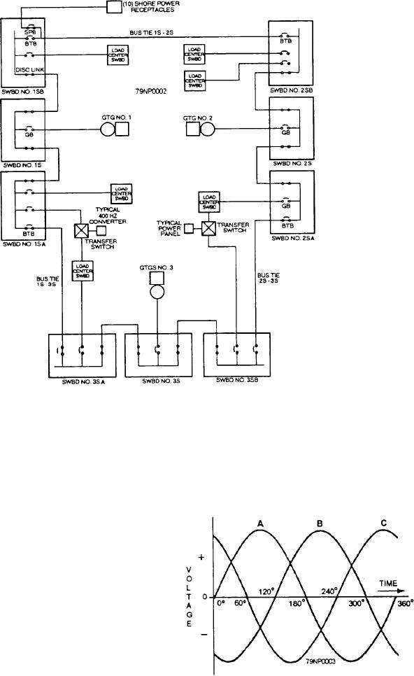
Figure 3-2.--Power distribution in a gas turbine powered DDG.
pumps, driven by three-phase motors. The phase
Information plates without markings are provided for
sequence of the power supply throughout a ship is
spare circuit breakers mounted in distribution panels.
Panel switches controlling circuits that are de-energized
always ABC (regardless of whether power is supplied
during darkened ship operations are marked
from any of the switchboards or from the shore power
DARKENED SHIP. The ON and OFF position of these
switches are marked LIGHT SHIP and DARKENED
SHIP, respectively.
Circuit information plates are provided inside fuse
boxes (next to each set of fuses). They show the circuit
controlled, the phases or polarity, and the ampere rating
of the fuse.
Phase Sequence
The phase sequence. in naval ships is ABC (fig. 3-3);
that is, the maximum positive voltages on the three
phases are reached in the order A, B, and C. Phase
sequence determines the direction of rotation of
three-phase motors. Therefore, a reversal of the phase
Figure 3-3.--Sine curve for three-phase circuit.
sequence could cause damage to loads, especially
3-3