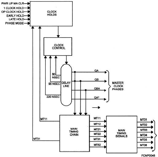
Figure 5-3 is an example block diagram of timing
circuitry used in a computer’s CPU.
Master Clock
From our discussion in chapter 4, you learned that
the master clock can be either a single- or multiple phase
master clock. A single-phase master clock can then be
used to trigger a single-shot multivibrator that is used
throughout the computer to enable and disable circuits
in whatever sequence is necessary to properly execute
the computer’s operations. Multiple-phase master
clocks can use a pulse generator or delay line oscillator
to generate two or more clock phases. A delay line
oscillator will generate two basic clock phases and any
additional phases are derived from taps on the delay line
oscillator.
Whether a pulse generator or delay line oscillator
is used, they generate multiple phases sometimes
referred to as odd q1 (CP1) and even phases q2 (CP0)
or lettered phases (qA, qB, or (qBA). These phases from
the master clock are then used to initiate the main timing
chain flip-flops. The master clock in a computer can be
suspended under certain conditions; the way it can
happen varies with the type of computer. With a
microcomputer, it is usually done by removing power
to the computer.
With a larger mainframe or
minicomputer, you will need to remove the power
works, too. However, certain types of HOLDS,
MASTER CLEARS, and operating MODES selected
at a console can also suspend master clock oscillations.
Refer to your computer’s technical manual for details.
Refer again to figure 5-3 for an example.
Main Timing Chain
The main timing chain consists of flip-flops
arranged in a ring counter. It is used to count master
clock phases. The flip-flops used in the main timing
can be set and cleared by the two basic master clock
phases and any additional master clock phases. The
design of the computer determines how this is
accomplished. The main timing (MT) chain is often
Figure 5-3.—Example block diagram of timing circuitry used in a computer’s CPU.
5-4


