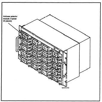
up to 20 stations. More than one address control
indicator may be installed in a system to provide the
ability to interrogate more than 20 stations.
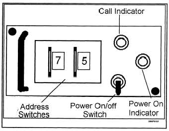
Each address selector module has two thumb
wheel switches in which one of 64 octal addresses
may be entered (address 00 and 77 octal are invalid).
Also, each address selector module has a power on/off
switch, a power on indicator lamp, and a call
indicator, as shown in figure 4-18.
When a unit is configured as the NCS, the
operator enters all the assigned addresses of the net
participating units into the address selector modules,
and turns on each module with a valid address. Once
the roll call mode is initiated, the DTS will check each
module sequentially. If the power of the module is on
and a valid address is entered, the address is sent to
the DTS for use in an interrogation message. If the
power switch is in the OFF position, that module is
skipped, even if it contains a valid address. When
enabled by the DTS, the address selector module
sends the address entered in the thumb wheels to the
DTS and the call indicator light. The call indicator
will remain lit until the DTS sequences to the next
address module.
CDS INPUT/OUTPUT CONTROL
The data terminal set controls the exchange of
data with the CDS computer. As described earlier,
i n p u t / o u t p u t c o m m u n i c a t i o n s p r o t o c o l is
accomplished through the use of external interrupts.
The prepare-to-transmit data interrupt, the prepare-to-
receive data interrupt, and the end-of-receive data
interrupt are used to control most of the DTS to the
computer interface.
CDS Computer Input (Receive) Data Cycle
The input data cycle is initiated by the DTS.
When the DTS recognizes the second frame of the
start code, it sets the prepare to receive data interrupt
on the input data lines and sets the external interrupt
line. The computer acknowledges the receipt of the
interrupt by sending an input data acknowledge (IDA)
to the DTS.
Figure 4-17.—The Address Control Indicator C9062/U.
Upon receipt of the first message frame, the DTS
demodulates the 24-bit word and places it on the input
data lines, along with the two error detection and
correction bits. Once the data is placed on the input
data lines, the DTS sets the input data request (IDR)
line. The computer will sample the data and send an
IDA. This process repeats for all frames of the
message. The first frame of the stop code is also
treated as a message frame and sent to the CDS
computer. When the DTS recognizes the second
frame of the stop code, it will place the end of receive
Figure 4-18.—An address selector module.
4-17


