atmospheric levels in the ionosphere account for a
large part of these energy losses. There are two other
types of losses that also significantly affect
propagation. These losses are known as ground
reflection losses and freespace loss. The combined
effect of absorption ground reflection loss, and
freespace loss account for most of the losses of radio
transmissions propagated in the ionosphere.
GROUND REFLECTION LOSS
When propagation is accomplished via multihop
refraction, rf energy is lost each time the radio wave
is reflected from the earth’s surface. The amount of
energy lost depends on the frequency of the wave, the
angle of incidence, ground irregularities, and the
electrical conductivity of the point of reflection.
FREESPACE LOSS
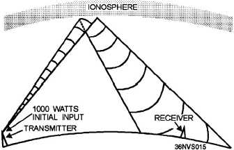
Normally, the major loss of energy is because of
the spreading out of the wavefront as it travels from
the transmitter. As distance increases, the area of the
wavefront spreads out, much like the beam of a
flashlight. This means the amount of energy
contained within any unit of area on the wavefront
decreases as distance increases. By the time the
energy arrives at the receiving antenna, the
wavefront is so spread out that the receiving antenna
extends into only a small portion of the wavefront.
This is illustrated in figure 1-15.
FREQUENCY SELECTION
You must have a thorough knowledge of radio-
wave propagation to exercise good judgment when
selecting transmitting and receiving antennas and
operating frequencies. Selecting a usable operating
frequency within your given allocations and
availability is of prime importance to maintaining
reliable communications.
For successful communication between any two
specified locations at any given time of the day, there
is a maximum frequency, a lowest frequency and an
optimum frequency that can be used.
Figure 1-15.—Freespace loss principle.
MAXIMUM USABLE FREQUENCY
The higher the frequency of a radio wave, the
lower the rate of refraction by the ionosphere.
Therefore, for a given angle of incidence and time of
day, there is a maximum frequency that can be used
for communications between two given locations. This
frequency is known as the MAXIMUM USABLE
FREQUENCY (muf).
Waves at frequencies above the muf are
normally refracted so slowly that they return to earth
beyond the desired location or pass on through the
ionosphere and are lost. Variations in the ionosphere
that can raise or lower a predetermined muf may
occur at anytime. his is especially true for the highly
variable F2 layer.
LOWEST USABLE FREQUENCY
Just as there is a muf that can be used for
communications between two points, there is also a
minimum operating frequency that can be used
known as the LOWEST USABLE FREQUENCY (luf).
As the frequency of a radio wave is lowered, the rate
of refraction increases. So a wave whose frequency is
below the established luf is refracted back to earth at
a shorter distance than desired, as shown in figure 1-
16.
1-13