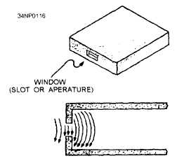
Figure 3-43.—Slot coupling in a waveguide.
Minimum reflections occur when energy is injected
or removed if the size of the slot is properly propor-
tioned to the frequency of the energy.
After learning how energy is coupled into and out
of a waveguide with slots, you might think that leaving
the end open is the most simple way of injecting or
removing energy in a waveguide. This is not the case,
however, because when energy leaves a waveguide,
fields form around the end of the waveguide. These
fields cause an impedance mismatch which, in turn,
causes the development of standing waves and a drastic
loss in efficiency.
Various methods of impedance
matching and terminating waveguides will be covered
in the next section.
WAVEGUIDE IMPEDANCE
MATCHING
Waveguide transmission systems are not always
perfectly impedance matched to their load devices.
The standing waves that result from a mismatch cause
a power loss, a reduction in power-handling capability,
and an increase in frequency sensitivity. Imped-
ance-changing devices are therefore placed in the
waveguide to match the waveguide to the load. These
devices are placed near the source of the standing
waves.
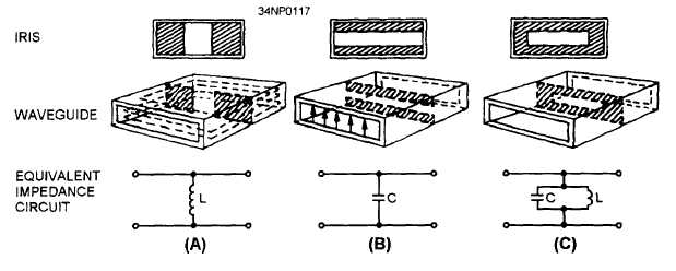
Figure 3-44 illustrates three devices, called irises,
that are used to introduce inductance or capacitance
into a waveguide. An iris is nothing more than a metal
plate that contains an opening through which the waves
may pass. The iris is located in the transverse plane
of either the magnetic or electric field.
An inductive iris and its equivalent circuit are
illustrated in figure 3-44, view A. The iris places a
shunt inductive reactance across the waveguide that
is directly proportional to the size of the opening.
Notice that the inductive iris is in the magnetic plane.
The shunt capacitive reactance, illustrated in view
B, basically acts the same way. Again, the reactance
is directly proportional to the size of the opening, but
the iris is placed in the electric plane. The iris,
illustrated in view C, has portions in both the magnetic
Figure 3-44.—Waveguide irises.
3-20