CHAPTER 1
INTRODUCTION TO BASIC RADAR
The Navy Electricity and Electronics Training
Series (NEETS) modules, especially module 18, Radar
Principles, provide information that is basic to your
understanding of this volume. This volume will discuss
radar and radar systems as you may encounter them as
an Electronics Technician at your command. You
should refer to NEETS module 18 and Electronics
Installation and Maintenance Book (EIMB), Radar and
Electronic Circuits, on a regular basis to ensure that you
have a complete understanding of the subject matter
covered in this volume.
As an Electronics Technician, Second Class, and
possible work center supervisor, you must understand
the basic radar principles and safety requirements for
radar maintenance. However, due to luck of the draw,
your first assignment may not afford you exposure to
radar systems. Our intention with this volume is NOT
to teach you every radar system the Navy uses, but
simply to familiarize you with the radars and their
general maintenance principles.
You will be able to identify the equipment
requirements and general operation of the three basic
radar systems covered in chapter 1. You’ll become
familiar with the nomenclature of specific radars used
in the Navy today as we discuss them in chapter 2. Then,
armed with all that knowledge you will easily grasp the
system concepts addressed in chapter 3. And before you
go out to tackle the radar world, chapter 4 will give you
necessary safety information specific to radar
maintenance.
When you arrive at your next command as a second
class with work center responsibilities for a radar
maintenance shop, you will be ready.
BASIC RADAR CONCEPTS
The term radar is an acronym made up of the words
radio, detection, and ranging. It refers to electronic
equipment that detects the presence, direction, height,
and distance of objects by using reflected
electromagnetic energy.
The frequency of
electromagnetic energy used for radar is unaffected by
darkness and also penetrates weather. This permits
radar systems to determine the position of ships, planes,
and land masses that are invisible to the naked eye
because of distance, darkness, or weather.
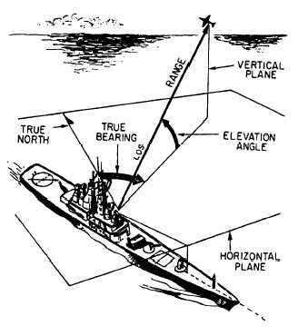
Radar systems provide only a limited field of view
and require reference coordinate systems to define the
positions of the detected objects. Radar surface angular
measurements are normally made in a clockwise
direction from TRUE NORTH, as shown in figure 1-1,
or from the heading line of a ship or aircraft. The actual
radar location is the center of this coordinate system.
Figure 1-1 contains the basic terms that you need to
know to understand the coordinate system. Those terms
are defined in the following paragraph.
The surface of the earth is represented by an
imaginary flat plane, known as the HORIZONTAL
PLANE, which is tangent (or parallel) to the earth’s
surface at that location. All angles in the up direction
are measured in a secondary imaginary plane, known as
the VERTICAL PLANE, which is perpendicular to the
horizontal plane. The line from the radar set directly to
the object is referred to as the LINE OF SIGHT (LOS).
The length of this line is called RANGE. The angle
Figure 1-1.—Radar reference coordinates.
1-1


